AFCAD v2.21 Просмотр ZIP-архива
ReadMe.htm
<html>
<head>
<meta http-equiv="Content-Type" content="text/html; charset=windows-1252">
<meta name="Generator" content="Microsoft FrontPage 4.0">
<meta name="ProgId" content="FrontPage.Editor.Document">
<title>AFCAD</title>
<style type="text/css">body { margin-left: 10%; margin-right: 10% }
h1, h2, h3, h4, h5, h6 { margin-left: -4% }
h3 { margin-top: 2em }
h3.noleadingblank { margin-top: 1em }
</style>
</head>
<body link="#0000ff" vlink="#800080">
<font face="Arial">
<h1 align="CENTER" style="border: 4 solid #0033CC; padding-left: 20; padding-top: 32; padding-bottom: 32"><font color="#003399"><font size="6">AFCAD<br>
</font><font size="5"><br>
Version 2.21 - for FS2004<br>
User Manual</font></font></font></h1>
<font face="Arial">
<h3 style="border: 3 solid #0033CC; padding-left: 10; padding-top: 10; padding-bottom: 10"><font color="#0033CC">Contents</font></h3>
</font>
<ul>
<li><a href="#ChangesForThisRelease">Changes For This Release</a></li>
</ul>
<font face="Arial">
<p><b>General Program Usage</b></p>
</font>
<ul>
<li><a href="#InstallingAFCAD">1. Installing AFCAD 2</a></li>
<li><a href="#Uninstalling">2. Uninstalling</a></li>
<li><a href="#WhatIsAFCAD">3. What is AFCAD?</a></li>
<li><a href="#WhatYouCanDoWithThisProgram">4. What You Can Do With This
Program</a></li>
<li><a href="#WhatWithSubsequentReleases">5. What You Will Be Able To Do With
Subsequent Releases of AFCAD</a></li>
<li><a href="#CompatibilityWithEarlierAFCADFiles">6. Compatibility With
Earlier AFCAD Files</a></li>
<li><a href="#FSUIPC">7. FSUIPC</a></li>
<li><a href="#UsingAFCADandFlightSimulatorTogether">8. Using AFCAD and Flight
Simulator Together</a></li>
<li><a href="#StartingAFCAD">9. Starting AFCAD and Opening an Airport</a></li>
<li><a href="#SavinganAirport">10. Saving an Airport</a></li>
<li><a href="#Re-OpeninganAirport">11. Re-Opening an Airport</a></li>
<li><a href="#DeletingandRestoringAirports">12. Deleting and Restoring
Airports</a></li>
<li><a href="#Undo">13. Undo - The Most Important Command</a></li>
<li><a href="#ManipulatingtheAFCADDisplay">14. Manipulating the AFCAD Display</a></li>
<li><a href="#SlewinginFlightSimulator">15. Slewing in Flight Simulator</a></li>
<li><a href="#LockMode">16. Lock Mode</a></li>
<li><a href="#StatusBar">17. Status Bar</a></li>
<li><a href="#Options">18. Options</a></li>
<li><a href="#MarkersGuidelinesAndMeasurements">20. Markers, Guidelines, and
Measurements</a></li>
<li><a href="#Add-onSceneryandAFCAD">21. Add-on Scenery and AFCAD</a></li>
<li><a href="#AirportProperties">22. Airport Properties</a></li>
</ul>
<font face="Arial">
<p><b>Working With Airport Objects</b></p>
</font>
<ul>
<li><a href="#AnatomyofanAirport">23. Anatomy of an Airport</a></li>
<li><a href="#SceneryPresentation">24. Scenery Presentation</a></li>
<li><a href="#SelectingObjects">25. Selecting Objects</a></li>
<li><a href="#MovingObjects">26. Moving Objects</a></li>
<li><a href="#DeletingObjects">27. Deleting Objects</a></li>
<li><a href="#AirportProperties">28. Object Properties</a></li>
<li><a href="#Nodes,Links,andParking">29. Nodes, Links, and Parking</a></li>
<li><a href="#Nodes">30. Nodes</a></li>
<li><a href="#Links">31. Links</a></li>
<li><a href="#Designators">32. Designators</a></li>
<li><a href="#TaxiwaySigns">33. Taxiway Signs</a></li>
<li><a href="#Parking">34. Parking</a></li>
<li><a href="#ParkingAssignmentsforAIAircraft">35. Parking Assignments for AI
Aircraft</a></li>
<li><a href="#CustomParkingSpecs">36. Custom Parking Specs</a></li>
<li><a href="#AircraftEditor">37. Aircraft Editor</a></li>
<li><a href="#Aprons">38. Aprons</a></li>
<li><a href="#ApronEdgeLights">39. Apron Edge Lights</a></li>
<li><a href="#Runways">40. Runways</a></li>
<li><a href="#RunwayMarkings">41. Runway Markings</a></li>
<li><a href="#RunwayLights">42. Runway Lights</a></li>
<li><a href="#VASI">43. VASI</a></li>
<li><a href="#Helipads">44. Helipads</a></li>
<li><a href="#StartLocations">45. Start Locations</a></li>
<li><a href="#TowerViewpoint">46. Tower Viewpoint</a></li>
<li><a href="#CommFrequencies">47. Comm Frequencies & ATC</a></li>
<li><a href="#Navaids">48. Navaids</a></li>
</ul>
<font face="Arial">
<p><b><a name="SBS">Step-by-Step Instructions</a></b></p>
</font>
<ul>
<li><a href="#InstallingDownloadedAirports">49. Installing Downloaded Airports</a></li>
<li><a href="#AddingATCtoanAirport">50. Adding ATC to an Airport</a></li>
<li><a href="#AddingParkingtoanAirport">51. Adding Parking to an Airport</a></li>
<li><a href="#CreatingaNewAirportFromScratch">52. Creating a New Airport From
Scratch</a></li>
</ul>
<font face="Arial">
<p><b>Final Notes</b></p>
</font>
<ul>
<li><a href="#FaultFinder">53. Fault Finder and Final Checks</a></li>
<li><a href="#ProblemsandQ & A">54. Problems and Q & A</a></li>
<li><a href="#ReportingProblems">55. Reporting Problems</a></li>
<li><a href="#Copyright">56. Copyright</a></li>
</ul>
<font face="Arial">
<h3 style="border: 3 solid #0033CC; padding-left: 10; padding-top: 10; padding-bottom: 10"><a name="ChangesForThisRelease"><font color="#0033CC">Changes
For This Release 2.</font></a><font color="#0033CC"><a name="ChangesForThisRelease">2</a>1</font></h3>
</font>
<p><b>Navaids</b><br>
AFCAD can now create, move, and modify <a href="#Navaids">navaids</a>.
This includes ILS (LOC / GS / DME), VOR / DME, marker beacons (OM / MM / IM /
BC), and NDBs. These changes will appear in the Flight Simulator Map View
and GPS windows and your aircraft instruments will recognise the
changes. There are, however, certain limitations with regard to
navaid changes, as follows:</p>
<p>Creation: AFCAD can create any of the above navaids at any location.</p>
<p>Modification: AFCAD can move or modify any navaids that you create. It can
also move or modify all stock navaids <i>except for marker beacons</i>, stock
marker beacons cannot be changed in any way. You cannot change the
identifiers for any stock navaids but almost all other parameters can be
changed.</p>
<p>Deletion: AFCAD can delete any navaids that you create, but it cannot delete
any stock navaids.</p>
<p><b>Helipads</b><br>
AFCAD can now create, move, modify or delete <a href="#Helipads">helipads</a>.
Helipads will show up in the Go To Airport start list if you associate <a href="#StartLocations">Start
Locations</a> for them. Note that AI
helicopters cannot inherently be made to work as AI.</p>
<p><b>Lat / Long Grid</b><br>
AFCAD can now display a latitude / longitude grid. This can be enabled or
disabled from the View menu, or by pressing the G key. The grid divisions
can be adjusted from the <a href="#Options">Options</a> window, under the Tools menu.</p>
<p><b>File Name in Title Bar</b><br>
The name of the file for the currently open airport is now shown in the title
bar. If a stock airport was opened and not yet saved then the title bar
will show "stock" for the file.</p>
<font face="Arial">
<h3 style="border: 3 solid #0033CC; padding-left: 10; padding-top: 10; padding-bottom: 10"><font color="#0033CC">Changes
For Previous Release 2.11</font></h3>
</font>
<p><b>Apron Surfaces and Lights</b><br>
AFCAD can now create, move, modify and delete <a href="#Aprons">apron surfaces</a>
and <a href="#ApronEdgeLights">apron edge lights</a>. Apron surfaces are used
for more than just aprons, they are frequently used wherever extra pavement is
required around airports, such as wide areas on taxiways, turn-around bays on
runways, extra large fillets at taxiway junctions, etc. Apron surfaces can
be polygons of practically any shape and size. Aprons often have edge
lights, and those can be created and modified separately from the apron
surfaces.</p>
<p><b>Creating New Airports<br>
</b>This version can create a <a href="#CreatingaNewAirportFromScratch">new
airport</a> from scratch using the <i>New Airport</i> item under the File menu.
It is important to note that this version of AFCAD cannot create taxiway signs
or airport structures for new airports (or existing airports), so airports
created using this method will be somewhat bare, but these features will be
added later. Also, AFCAD does not yet create flattening polygons or
exclusions, so until that is available you will have to use flattening and/or
exclusion switches in the scenery.cfg file or create them using another scenery
tool. The New Airport feature can be used to create facility airports for
existing sceneries created using older scenery tools. In that case the
AFCAD-created airport will not be visible and the older format scenery will
automatically appear instead, but the AFCAD airport data will still be available
for AI and ATC.</p>
<p><b>Markers and Guidelines</b><br>
New <a href="#MarkersGuidelinesAndMeasurements">marker and guideline</a> tools
have been provided. These are not part of airport data but are strictly
used as reference points and ruler lines for drawing and layout.</p>
<p><b>Measuring Tool Changed</b><br>
Previous AFCAD versions had a measuring tool which was called from right-click
pop up menu. This has been removed. In its place, the status bar
will show the distance from the last marker placed on the screen to the current
mouse position, and the angle between the last two markers and the mouse will
also be shown.</p>
<p><b>Keyboard help</b><br>
A list of all special function keystrokes is available under the Help menu.</p>
<p><b>Airport Indexing Problems</b><br>
A problem has been fixed that could cause the Open Airport window to show no
airports.</p>
<p><b>Various bugs have been fixed</b></p>
<font face="Arial">
<h3 style="border: 3 solid #0033CC; padding-left: 10; padding-top: 10; padding-bottom: 10"><font color="#0033CC">Changes
For Previous Release 2.0</font></h3>
</font>
<p><b>Working with visible scenery</b><br>
Previous Flight Simulator versions had two types of scenery data for airports:
visible scenery and invisible facility data and maps. These two types of data
were completely separate, in separate sets of files, and they had no connection.
ATC and AI used the invisible facility data and knew nothing about the visible
scenery, so you could have a complete airport operation set up in an empty field
with AI and ATC and no visible airport. Conversely, you could have a complete
visible airport that did not appear in the FS Map View or start window and had
no AI or ATC. Now the same scenery data creates both visible scenery and
information for AI, ATC, Map View and GPS displays.</p>
<p>This means that AFCAD can change some -- but not all -- visible airport
scenery. It has been given more of a WYSIWYG (What you see is what you
get) format so that users can immediately see the results of changing runways,
taxiways, marking, lights and other elements without having to restart FS each
time.</p>
<p>FS2004 still accepts old BGLC format scenery files layered over the stock
scenery, and in that case AFCAD will not affect the visible scenery created in
BGLC, but it can still be used to alter the facility information that AI and ATC
uses from the underlying stock scenery file.</p>
<p><b>AFCAD changes are no longer inserted in stock files</b><br>
Unlike visible scenery which could be layered over stock scenery, facility data
for FS2002 could not be properly layered. This meant that AFCAD had to insert
modified facility data directly into stock facility files to replace the
original data. This was a cumbersome method that required a special installer
and cataloguing and backup functions to be able to remove modified airports or
restore whole stock scenery files. This is no longer a problem with FS2004. An
airport changed with AFCAD is now output as a separate single-airport .bgl file
instead of being inserted into stock files. By default, .bgl files for modified
airports are deposited in the FS Addon Scenery folder and will automatically
override the corresponding stock airport when FS is next started. File
distribution no longer requires export files and a special installer, the .bgl
file itself can be posted and the user can copy it to the Addon Scenery folder,
or another appropriate location. To remove a modified airport from the system
and restore the stock airport, simply remove the .bgl file.</p>
<p>Consequently, the import/export and cataloguing functions have been removed
from AFCAD and the AFInstaller is no longer supplied.</p>
<p><b>Mouse wheel and wheel button</b><br>
AFCAD now uses the mouse wheel to quickly zoom in and out, and holding down the
Ctrl key allows you to use the mouse wheel to rotate the display. Pressing the
mouse wheel-button on the window allows you to grab the viewport and drag it to
another location around the airport.</p>
<p><b>Parking codes</b><br>
AFCAD can utilize the new parking codes feature of FS2004. This allows you to
assign gates to specific airlines or other designated aircraft. Parking codes
can be assigned to each gate and corresponding codes can be entered in the
aircraft.cfg files for individual aircraft ‘paints’ to direct them to park
at gates with the same code. Multiple codes can be assigned to a gate to specify
several different airlines that can park there, in order of priority.</p>
<p>This means that the previous ‘Radius’ method is no longer required to
configure airline parking; however, radius is still used by FS as a determining
factor for which sized aircraft can fit in which parking spots.</p>
<p>To facilitate parking configuration, the Parking Specifications (Parking
Specs) feature of the previous AFCAD has been moved from the AFCAD config file
to a separate file: ParkingSpecs.txt . This file defines parking codes for
airlines and other aviation groups, allowing parking to be assigned by name. A
pre-defined parking specs file is provided courtesy of the Project AI (PAI)
group. Thanks to Matt Fox, Graham Jackson and Jorge Buchelli and others for
compiling this file. The file covers most of the world's airlines. Because
airlines come and go over time, users should check the <a href="http://www.Projectai.com">Project
AI</a> web site once or twice a year to get updated versions of this file.</p>
<p><b>Parking Labels</b><br>
Labels can now be displayed on all parking spots using the new ‘Parking Types’
and ‘Parking Codes’ items under the View menu. You can also use the ‘P’
key to cycle the parking labels between Types, Codes, and off.</p>
<p><b>Aircraft Editor Tool</b><br>
Available under the Tools menu, this window allows you to alter AI aircraft
parameters that affect where they will park. This can be done for any of the
stock or add-on aircraft models you have installed. It allows you set a parking
code, parking type, and radius for an aircraft. These are the three main
determinants for where an aircraft will park.</p>
<p><b>Night layout for lights</b><br>
Since AFCAD can now add or modify all runway, taxiway, approach and VASI
lighting, the display can be changed to a night mode to show lighting
configurations. Use the ‘Show Lights’ item under the View menu. Or press the
‘L’ key to toggle this feature on or off.
<p><font face="Arial"></p>
<h2 style="border: 4 solid #0033CC; padding-left: 10; padding-top: 25; padding-bottom: 25"><font color="#0033CC">General
Program Usage</font></h2>
<h3 style="border: 3 solid #0033CC; padding-left: 10; padding-top: 10; padding-bottom: 10" class="noleadingblank"><a name="InstallingAFCAD"><font color="#0033CC">1.
Installing AFCAD 2</font></a></h3>
</font>
<p>NOTE: This version of AFCAD is for <u>FS2004 ONLY</u>. Version 1.4 works with
FS2002 .</p>
<p>If you have already installed a version of AFCAD 2 then you can unzip this
release to the same folder.</p>
<p>If this is the first installation of AFCAD 2 then create a folder anywhere
you want and unzip AFCAD 2 to that folder. If you had previously installed the
original AFCAD (1.4 or earlier) you could use the same folder, but AFCAD 2 does
not use the same types of files so to avoid confusion you may want to clear out
the folder and remove any residual files. If you want to work with both FS2002
and FS2004 then you should keep AFCAD 1 and 2 separate.</p>
<font face="Arial">
<h3 style="border: 3 solid #0033CC; padding-left: 10; padding-top: 10; padding-bottom: 10"><a name="Uninstalling"><font color="#0033CC">2.
Uninstalling</font></a></h3>
</font>
<p>AFCAD doesn’t register itself with Windows, so if you want to get rid of it
you can just delete the folder it is in and all the files.</p>
<font face="Arial">
<h3 style="border: 3 solid #0033CC; padding-left: 10; padding-top: 10; padding-bottom: 10"><a name="WhatIsAFCAD"><font color="#0033CC">3.
What is AFCAD?</font></a></h3>
</font>
<p>It is a freeware CAD-style program that allows you to modify the facility
data, and some of the visible scenery, used in Microsoft Flight Simulator (FS).
The facility data that AFCAD works with is used by ATC to control user and AI
aircraft at airports and to assign parking. It also controls the airport
information that you see on the ‘map view’, GPS screen, flight planner, and
start position set-up window in Flight Simulator. The visible scenery that AFCAD
can modify includes runways, taxiways, aprons, and all associated markings and
lights. More airport scenery elements will be added in subsequent releases.</p>
<font face="Arial">
<h3 style="border: 3 solid #0033CC; padding-left: 10; padding-top: 10; padding-bottom: 10"><a name="WhatYouCanDoWithThisProgram"><font color="#0033CC">4.
What You Can Do With This Program</font></a></h3>
</font>
<p><b><a href="#Runways">Runways</a></b><br>
You can add, delete, move or modify runways. This includes all runway markings,
lighting, approach lights, VASI and similar visual landing aids. Although you
cannot create your own runway surface textures, you can choose from an array of
stock surface types from concrete to water.</p>
<p><b><a href="#RunwayProperties">Different runways for takeoffs and landings</a></b><br>
At airports that have parallel runways, you can change which runways ATC assigns
to user and AI aircraft for takeoffs and landings. Note that you cannot make ATC
use crossing runways or runways at different angles simultaneously.</p>
<p><b><a href="#Nodes,Links,andParking">Taxiways</a></b><br>
You can add, delete, move or modify taxiways. This includes taxiway markings,
lighting, surface type, and designations (e.g. taxiway "B2"). In
addition to the visual appearance and location of taxiways, the routing of
taxiways also controls how ATC routes user and AI aircraft around the airport.</p>
<p><b><a href="#Aprons">Aprons</a></b><br>
You can add, delete, move or modify apron surfaces and <a href="#ApronEdgeLights">apron
edge lights</a>. Apron surfaces can be used anywhere extra pieces of
pavement are required around airports, not just at terminal buildings.</p>
<p><b><a href="#Parking">Parking</a></b><br>
You can add parking spots (gate and ramp parking) and modify or delete existing
parking spots at airports for your own use, or to increase the AI levels at an
airport. Parking can be added at airports that do not currently have it. Any
number of parking spots can be added. You can also adjust gate parking so that
aircraft doors mate with existing boarding bridges (jetways). Parking is
required in order for AI to operate at an airport, so adding parking will also
allow you to program AI to use airports that do not currently have it.</p>
<p><b><a href="#ParkingAssignmentsforAIAircraft">Airline Gate Assignments</a></b><br>
Microsoft added to FS2004 the capability to assign specific airlines to specific
gates. You can also designate classes of aircraft to use certain classes of
parking, such as GA aircraft to ramp parking, cargo aircraft to cargo parking
and military aircraft to mil parking .</p>
<p><b><a href="#CommFrequencies">ATC and communications</a></b><br>
You can add, delete, and modify communications frequencies. Adding a tower
and/or ground control frequency is all that is needed to add ATC to any airport
that does not already have it, you do not need an actual control tower scenery
object to have ATC operation. Note that FS2002 required ATC to be present at an
airport in order for AI to operate there but FS2004 no longer has that
restriction, AI can now operate even at uncontrolled airports.</p>
<p><b><a href="#Navaids">Navaids</a></b><br>
You can add new navaids or modify stock navaids (ILS, Marker Beacons, VOR / DME, NDBs).</p>
<p><b><a href="#Helipads">Helipads</a></b><br>
You can add new helipads or modify stock helipads.</p>
<p><b><a href="#StartLocations">Start locations</a></b><br>
Every airport comes with default start locations for your aircraft at the end of
each runway. These can be changed to be at different locations, such as at the
taxiway entrance to a runway.</p>
<p><b><a href="#TowerViewpoint">Control tower view</a></b><br>
The location for the control tower view of your aircraft (selected by pressing
the ‘S’ key twice in FS) can be changed. This can be placed at the actual
control tower location, if there is a tower, or any other location or elevation.</p>
<p><b><a href="#ShiftingAdd-OnAirports">Shifting airports</a></b><br>
Some third party replacement airports do not line up properly with stock Flight
Simulator airports. This can cause the AI to taxi and take off and land on the
grass instead of runways and taxiways. AFCAD allows you to shift the entire
airport, or realign specific taxiways, runways and parking to correct this.</p>
<p>Note that although the taxiway modification capability is fully implemented
in this release, its usefulness is limited by the inability to move or change
taxiway signs. The ability to change taxiway signs will be added in a subsequent
release.<font face="Arial">
<h3 style="border: 3 solid #0033CC; padding-left: 10; padding-top: 10; padding-bottom: 10"><font color="#0033CC"><a name="WhatWithSubsequentReleases">5.
What You Will Be Able To Do With Subsequent Releases of AFCAD</a></font></h3>
</font>
<p>AFCAD is a work in progress. The ability to modify the following elements
will be added to subsequent releases.</p>
<p><b>Taxiway Signs</b><br>
The ability to create, delete, move or modify taxiway signs will be added.</p>
<p><b>Airport structures</b><br>
The ability to add, delete, or move airport structures will be added.<p><b>Exclusions
and Flattening</b><br>
The ability to exclude existing scenery (and Autogen trees etc.) will be added, as well
as the ability to create flattening polygons.<font face="Arial">
<h3 style="border: 3 solid #0033CC; padding-left: 10; padding-top: 10; padding-bottom: 10"><font color="#0033CC"><a name="CompatibilityWithEarlierAFCADFiles">6.
Compatibility With Earlier AFCAD Files</a></font></h3>
</font>
<p>AFCAD 2 can't use export files produced by AFCAD 1, and there will likely be
no method provided to convert them for use with AFCAD 2. This is because FS2002
facility data was more simplistic than FS2004 data and FS2002 did not control
any visual elements. There is no practical way to automate merging the visual
elements (markings, lights, surface textures, taxiway widths, runway extensions,
taxiway signs, aprons, airport structures, etc) of FS2004 airport data with the
simpler FS2002 facility data. The alternative would be a manual merging process,
and that would likely require as much or more work from the user to ‘fix up’
all the resulting problems than to re-do the airport from scratch.</p>
<font face="Arial">
<h3 style="border: 3 solid #0033CC; padding-left: 10; padding-top: 10; padding-bottom: 10"><font color="#0033CC"><a name="FSUIPC">7.
FSUIPC</a></font></h3>
</font>
<p>AFCAD can be used by itself for most airport design work but placing taxiways
and parking around buildings and structures can be awkward, as building are not
currently displayed on AFCAD. This makes it especially difficult to mate gate
parking spots with terminal boarding bridges. For that kind of work it is
preferable to link AFCAD with Flight Simulator using FSUIPC. You can start
Flight Simulator and ‘slew’ around an airport in a virtual aircraft and
crosshairs will move on the AFCAD map to show your location. Alternatively the
AFCAD map can be locked to your aircraft position like a moving map display.
FSUIPC is an add-on program that, among its other uses, allows third party
software to interface with Flight Simulator.</p>
<p>FSUIPC does not come with AFCAD but it can be downloaded from the following
site:</p>
<blockquote>
<p><a href="http://www.schiratti.com/dowson.html">www.schiratti.com/dowson.html</a></p>
</blockquote>
<p>Note that FSUIPC is free to users who only need to use its basic
functionality, such as linking AFCAD to FS. You only need to register and pay to
use its more advanced features, which are not required for AFCAD. AFCAD
registers itself with FSUIPC when it starts up.
<p>FSUIPC comes with documentation, but it is not necessary to read it for this
application. All you have to do is copy the file FSUIPC.dll into the MODULES
folder off your main Flight Simulator folder, for example:</p>
<blockquote>
<p>…\FS9\MODULES</p>
</blockquote>
<p>That’s all you need to do to link AFCAD with Flight Simulator.</p>
<font face="Arial">
<h3 style="border: 3 solid #0033CC; padding-left: 10; padding-top: 10; padding-bottom: 10"><font color="#0033CC"><a name="UsingAFCADandFlightSimulatorTogether">8.
Using AFCAD and Flight Simulator Together</a></font></h3>
</font><b><font face="Arial">
<p>Flipping Windows:</p>
</b></font>
<p>You can start either program first. Since most people don’t have enough
monitor space to have both the FS and AFCAD windows open side-by-side you can
have both windows maximised, and press the Alt+Tab key to flip back and forth
between them.</p>
<b><font face="Arial">
<p>Eliminating Pauses:</p>
</b></font>
<p>By default, Flight Simulator will go into pause mode whenever you leave the
FS window. It can be a nuisance un-pausing that window all the time but this can
be prevented by changing a Flight Simulator setting. On the FS <i>Settings
/ General</i> window, un-check the setting ‘Pause on task switch’.</p>
<font face="Arial">
<h3 style="border: 3 solid #0033CC; padding-left: 10; padding-top: 10; padding-bottom: 10"><font color="#0033CC"><a name="StartingAFCAD">9.
Starting AFCAD and Opening an Airport</a></font></h3>
</font>
<p>Start AFCAD and choose <i>Open Airport </i>from the File menu. When
this window opens for the first time AFCAD will index all the stock and add-on
scenery and that may take a minute or so. When opening the window on subsequent
occasions the delay will be much less.</p>
<p>The easiest way to open an airport is to enter the ICAO code (e.g. KLAX) in
the Airport ID box and click OK. If you do not know the airport code then you
can locate the city using the tree window on the left side. This lists all the
cities that Flight Simulator has. All the airports associated with a selected
city will be shown in the list box beside the tree window. If a city has more
than one airport then you must choose the one you want to work on before closing
the window.</p>
<p>When you open an airport, the scenery and facility data for that airport is
read into memory and you should be presented with a display similar to the one
below.</p>
<p><img border="0" src="Pics/A2Image5.GIF" width="600" height="406"></p>
<font face="Arial">
<h3 style="border: 3 solid #0033CC; padding-left: 10; padding-top: 10; padding-bottom: 10"><font color="#0033CC"><a name="SavinganAirport">10.
Saving an Airport</a></font></h3>
</font>
<p>Any changes you make to an airport are initially done only in memory. As long
as you don't do a ‘Save’, none of the changes you make will affect Flight
Simulator. If you want to experiment first before you do any serious work, then
just don’t save the airport you are working on.</p>
<p>When you do want to save changes to the airport then click Save or Save As. A
<i>Save As</i> window will open with a default file name assigned such as
AFC_KORD.bgl, and the destination folder will default to the FS9 <i>Addon
Scenery</i> folder. You would normally just click OK to accept the default
folder and file name unless you have a specific need to change them. Note that
unlike AFCAD 1, AFCAD 2 does not alter any stock FS9 files so there is no need
to backup anything. If you accidentally save an airport you didn't intend to
then all you have to do is delete the .bgl file that was created by AFCAD for
that airport.</p>
<p>Assuming you deposited the file in the default Addon Scenery folder, all you
have to do is start FS and go to that airport to observe the changes. If you
used another folder then you may have to enable that folder in the Scenery.cfg
file or using the Scenery Library window in FS.</p>
<p>If you have Flight Simulator open at the same time as AFCAD then after you
save the airport you will have to restart FS to see the changes.</p>
<p>You can save your ongoing work at any time. AFCAD also does auto-backups to a
separate file every couple of minutes and should recover after a failure or
improper shutdown.</p>
<font face="Arial">
<h3 style="border: 3 solid #0033CC; padding-left: 10; padding-top: 10; padding-bottom: 10"><font color="#0033CC"><a name="Re-OpeninganAirport">11.
Re-Opening an Airport</a></font></h3>
</font>
<p>If you have saved an airport and you subsequently try to re-open it by
entering the airport code on the Open Airport window, you will notice that the
airport appears twice in the list. The entry at the top of the list will be the
previously modified airport residing in the Addon Scenery folder, and the bottom
entry will be the stock airport. If multiple copies of an airport exist then the
list shows them ordered by scenery layer. Because the Addon folder is on a
higher layer it will be the one that you will actually ‘see’ in FS. This is
indicated by the stock airport in the lower layer being shown in faded print.
You can open either one, but you would normally open the modified airport again
if you want to make further changes.</p>
<p>Instead of using the Open Airport window to reopen an airport, you can just
choose the airport code from the Previously Open Airports List under the File
menu. That will automatically open the airport from the previously saved file in
the Addon Scenery folder, not the stock airport.</p>
<font face="Arial">
<h3 style="border: 3 solid #0033CC; padding-left: 10; padding-top: 10; padding-bottom: 10"><font color="#0033CC"><a name="DeletingandRestoringAirports">12.
Deleting and Restoring Airports</a></font></h3>
</font>To restore a stock airport or remove a new airport, simply remove the
.bgl file for that airport from the FS Addon Scenery folder (
.../FS9/Addon Scenery/Scenery/ ). If it is a new airport then the
airport may continue to be displayed on the Flight Simulator <i>Go To Airport</i>
window however, so to eliminate that residual airport listing just call up the
Scenery Library window from the FS <i>Settings</i>, and click the OK button to
close the window.<font face="Arial">
<h3 style="border: 3 solid #0033CC; padding-left: 10; padding-top: 10; padding-bottom: 10"><a name="Undo"><font color="#0033CC">13.
Undo - The Most Important Command</font></a></h3>
</font>
<p>Because everybody makes mistakes, the undo command is possibly the greatest
invention in computer science, after the spell checker. AFCAD can undo the last
12 changes using the Ctrl+Z key, or the undo button on the tool bar. There is
also a redo command, Ctrl+Y. Keep in mind that if you undo a few changes then
make a new change, you will not be able to redo the changes you ‘backed over’.</p>
<p>Another thing to keep in mind is that not every change shows up on the map
window. For example, if you changed a gate number using a Properties window, you
could undo that change later on and not see anything different on the map.</p>
<font face="Arial">
<h3 style="border: 3 solid #0033CC; padding-left: 10; padding-top: 10; padding-bottom: 10"><font color="#0033CC"><a name="ManipulatingtheAFCADDisplay">14.
Manipulating the AFCAD Display</a></font></h3>
</font><b><font face="Arial">
<p>Mouse Wheel:</p>
</b></font>
<p>Using the mouse wheel is the easiest way to manipulate the AFCAD display :</p>
<p><b>Zoom</b><br>
Turning the wheel in or out will quickly zoom in or out.</p>
<p><b>Rotate</b><br>
Turning the wheel with the Ctrl key pressed will rotate the display. Pressing
the Shift key instead will provide a finer rotation. Note that this rotate
action is disabled when AFCAD is locked to FS.</p>
<p><b>Drag</b><br>
Pressing the mouse wheel-button down on the window will activate a drag cursor
which allows you to drag the window viewpoint to a new location over the
airport. Note that this drag action is disabled when AFCAD is locked to FS.
Some mouse drivers may be pre-programmed to use the wheel mouse button for other
actions such as window swapping. If this occurs you can use the Windows
mouse control panel to set the wheel mouse action back to Autoscroll. </p>
<p>Tip: If you want to move the viewpoint a large distance it is usually easier
to zoom out first, allowing you to move the viewpoint in one high-level drag
rather than several low-level drags.</p>
<b><font face="Arial">
<p>Keys:</p>
</b></font>
<p>The following keys can be used to manipulate the AFCAD display if you don't
have a mouse wheel. Because AFCAD can work in conjunction with Flight Simulator
in ‘slew’ mode, where practical the same keys used to ‘slew’ around FS
are also used to move in AFCAD.</p>
<table border="0" cellspacing="20" height="277" cellpadding="0">
<tr>
<td height="255" valign="top">
<p align="CENTER"><img src="Pics/A2Image80.gif" width="100" height="164"><br>
Zoom out and in<br>
(also on the keypack)<br>
<br>
<br>
</td>
<td height="255" valign="top">
<p align="CENTER"><img src="Pics/A2Image81.gif" width="150" height="164"><br>
Shift the viewpoint*<br>
<br>
<br>
<br>
</td>
<td height="255" valign="top">
<p align="CENTER"><img src="Pics/A2Image82.gif" width="150" height="163"><br>
Rotate the display about the<br>
centre of the window*.<br>
The heading is shown in<br>
the status bar at the bottom<br>
of the window</td>
</tr>
</table>
<p>*Shift and rotate commands don’t work in ‘Lock’ mode. In that mode you
must shift and rotate the aircraft itself to move the map.</p>
<font face="Arial">
<h3 style="border: 3 solid #0033CC; padding-left: 10; padding-top: 10; padding-bottom: 10"><font color="#0033CC"><a name="SlewinginFlightSimulator">15.
Slewing in Flight Simulator</a></font></h3>
</font>
<p>To use AFCAD in conjunction with Flight Simulator open the FS ‘Create a
flight’ window and select the same airport you have open in AFCAD, pick an
aircraft, and start your flight at that airport. If you have FSUIPC installed
you should see red crosshairs appear on the AFCAD map where your aircraft is.</p>
<p>The most convenient FS mode for most airport work is in slew mode with the
top down view. Press ‘Y’ to enter slew mode and Ctrl+S key to change to
top-down view (both of these keys toggle in and out of those modes). In top-down
view mode you will also have red crosshairs on the FS window.</p>
<p>If you are not already familiar with FS slew mode, you can move your aircraft
all around, even through buildings and other aircraft without fear of damage.
You can use the joystick to move around, but here are some other keys you may
find useful in slew mode.</p>
<table border="0" cellspacing="20" height="199" cellpadding="0">
<tr>
<td height="177" valign="top">
<p align="CENTER"><img src="Pics/A2Image80.gif" width="100" height="164"><br>
Zoom out and in.<br>
Use with Shift key<br>
for finer control</td>
<td height="177" valign="top">
<p align="CENTER"><img src="Pics/A2Image81.gif" width="150" height="164"><br>
Accelerate the aircraft<br>
forward/backward<br>
and left/right.</td>
<td height="177" valign="top">
<p align="CENTER"><img src="Pics/A2Image82.gif" width="150" height="163"><br>
Rotate the aircraft<br>
CCW / CW<br>
</td>
</tr>
</table>
<table border="0" cellspacing="20" height="235" cellpadding="0">
<tr>
<td height="213" valign="top">
<p align="CENTER"><img src="Pics/A2Image83.gif" width="65" height="162"><br>
Raise / lower the<br>
aircraft altitude.<br>
(Most work can be<br>
done at ground level)</td>
<td height="213" valign="top">
<p align="CENTER"><img src="Pics/A2Image84.gif" width="150" height="165"><br>
Stop all slewing motion.<br>
Note that this also works<br>
from the AFCAD window.</td>
</tr>
</table>
<b><font face="Arial">
<p>Home:</p>
</font></b>
<p>In slew mode, you can sometimes find you have accidentally moved so far away
from the airport that you may not easily be able to get back. In that situation
you can change to the AFCAD window (Ctrl+Tab) and press the ‘Home’ key on
your keypad. That will return your aircraft in Flight Simulator to the Airport
Reference Point, the approximate centre of the airport.</p>
<b><font face="Arial">
<p>Jump Here:</p>
</b></font>
<p>Even more useful, you can put the mouse pointer on the AFCAD map wherever you
want to be, then use the right mouse button to open a pop up menu and select ‘Jump
Here’. The aircraft in Flight Simulator will immediately jump to that
location.</p>
<p><img border="0" src="Pics/A2Image6.GIF" width="347" height="150"></p>
<font face="Arial">
<h3 style="border: 3 solid #0033CC; padding-left: 10; padding-top: 10; padding-bottom: 10"><a name="LockMode"><font color="#0033CC">16.
Lock Mode</font></a></h3>
</font>
<p>So far you have been moving the aircraft crosshairs around a fixed map. In
lock mode, the crosshairs (the aircraft) will remain at the centre of the AFCAD
window, and the display will move with the aircraft, similar to a GPS moving map
window.</p>
<div align="justify">
<table border="0" cellpadding="10" width="100%">
<tr>
<td width="154" valign="middle"><img border="0" src="Pics/A2Image21.GIF" width="150" height="100"></td>
<td width="100%">Click the lock symbol on the toolbar to toggle lock mode</td>
</tr>
</table>
</div>
<p>Here is a map presentation using an FS aircraft aiming forward on the runway:</p>
<table border="0" width="384" cellpadding="10" height="221">
<tr>
<td width="211" height="199" valign="top">
<p align="CENTER"><img border="0" src="Pics/A2Image8.GIF" width="200" height="200"></p>
<p align="CENTER">Unlocked map<br>
(north at top)</td>
<td width="237" height="199" valign="top">
<p align="CENTER"><img border="0" src="Pics/A2Image9.GIF" width="200" height="200"></p>
<p align="CENTER">Locked map</td>
</tr>
</table>
<p>If you find you have slewed completely off the airport in this mode, you can
press the Home key in AFCAD to return to the airport centre.</p>
<font face="Arial">
<h3 style="border: 3 solid #0033CC; padding-left: 10; padding-top: 10; padding-bottom: 10"><a name="StatusBar"><font color="#0033CC">17.
Status Bar</font></a></h3>
</font>
<p>The status bar displays the Latitude and Longitude of the mouse pointer when
it is moved, or the lat/long of the red aircraft crosshairs when you are slewing
in Flight Simulator.</p>
<p>The status bar also displays the direction (rotation azimuth) of the window
in degrees true. That field will also show the heading of a parking spot or
start location symbol while you are rotating it.</p>
<p>If <a href="#MarkersGuidelinesAndMeasurements">reference markers</a> have
been placed somewhere on the window then the status bar will also display the
distance from the last marker drawn to the mouse pointer, and also the angle if
there are two or more markers on the window.</p>
<font face="Arial">
<h3 style="border: 3 solid #0033CC; padding-left: 10; padding-top: 10; padding-bottom: 10"><font color="#0033CC"><a name="Options">18.
Options</a></font></h3>
</font>
<p>The Options Window allows you to adjust various program parameters.</p>
<p><b><font face="Arial">Units - Feet or Metres:</font></b></p>
<p>Measurement units can be changed from feet to metres for <a href="#MarkersGuidelinesAndMeasurements">distance
measurements</a> on the status bar and all other windows that display elevations
or sizes. You can also select
to show only parking spot sizes in metres to correlate with other utilities that
display parking radiuses in metres.</p>
<p><b><font face="Arial">Lat / Long Format:
</font></b>
</p>
<p>You can set the display format for latitude and longitude to one of the
following formats:</p>
<pre> N49.12345
N49* 15.1234’
N49* 15’ 45.1234"
N49:15.1234
N49:15:45.1234</pre>
<p>Note: you can enter latitude and longitude in any of the those formats at any
time regardless of the lat / long format setting.<br>
When entering lat / long values, the degree, minute and seconds
symbols ( * ’ " ) are optional.</p>
<p><b><font face="Arial">Lat / Long Grid:
</font></b>
</p>
<p>The program will display a latitude / longitude grid which can be
enabled or disabled from the View menu, or by pressing the G key. You can
specify the number of grid divisions in either decimal minutes (e.g. 49
23.1, 49 23.2, 49 23.3 etc.) or seconds (49 23 06,
49 23
12, 49 23 18, etc.).</p>
<font face="Arial">
<h3 style="border: 3 solid #0033CC; padding-left: 10; padding-top: 10; padding-bottom: 10"><font color="#0033CC"><a name="MarkersGuidelinesAndMeasurements">20.
Markers, Guidelines, and Measurements</a></font></h3>
</font>
<p>Markers are small crosses that can be placed anywhere on the AFCAD
screen. They do not contribute to scenery in any way but they can be used
as reference aids while laying out airport features. Similarly, guidelines
are ruler lines that can be laid-down anywhere on the AFCAD screen. This can be
useful, for example, when trying to place several objects in a straight
line. Neither markers nor guidelines are saved in the airport file so if
you place some of these objects on the screen then close and re-open the
airport, they will be gone.</p>
<p><img border="0" src="Pics/A2Image102.GIF" width="300" height="100"></p>
<p>In addition to their use as visible reference points, markers are also used
as anchors for distance and angle measurements. The status bar will
display the distance from the last marker placed on the screen to the current
mouse position. If there are two or more markers then the angle between
the last two markers and the current mouse pointer will also be shown.</p>
<p><img border="0" src="Pics/A2Image103.GIF" width="200" height="100"></p>
<p>Markers and guidelines are created and manipulated in a manner very similar
to nodes and links. </p>
<b>
<p><font face="Arial">Creating Markers:</font></p>
<table border="0" cellpadding="10" width="100%">
<tr>
<td width="154" valign="middle"><img border="0" src="Pics/A2Image100.GIF" width="150" height="100"></td>
</b>
<td width="100%">Select the Marker Tool from the toolbar. The mouse pointer
will change to a ‘marker drop’ symbol. You can place markers anywhere
you want by clicking on the map window while the marker tool is active.</td>
</tr>
</table>
<p>You can also drop markers anywhere you want without leaving the Flight
Simulator window by slewing to the desired location and pressing the M key.
AFCAD traps the M key and will place a marker at that location.</p>
<b><font face="Arial">
<p>Creating Guidelines:</p>
</font></b>
<p>A Guideline can connect markers that have already been drawn, or you can run
a guideline between any two points and markers will be created at those points
if they don't already exist. A guideline will snap to an existing
marker if you start or end the line close to a marker.</p>
<table border="0" cellpadding="10" width="100%">
<tr>
<b>
<td width="154" valign="middle"><img border="0" src="Pics/A2Image101.GIF" width="150" height="100"></td>
</b>
<td width="100%">Select the Guideline Drawing Tool from the toolbar. The
mouse pointer will change to the guideline drawing symbol. Put the
cross on the location where you want to start the line, press the mouse
button and leave it down while you pull the line out to where you want it
to end, then release the mouse button.</td>
</tr>
</table>
<b><font face="Arial">
<p>Moving Markers and Guidelines:</p>
</font></b>
<p>Like most objects, you can move a marker or guideline by ‘grabbing’ it
with the mouse and dragging it. You must be in Pointer mode to do this -- select
the normal pointer from the toolbar.</p>
<b><font face="Arial">
<p>Deleting Markers and Guidelines:</p>
</font></b>
<p>You can delete a marker or guideline by selecting it and pressing the delete
key. You can delete all markers and guidelines on the screen by choosing <i>Delete
Markers and Guidelines</i> from the Edit menu, or by pressing Ctrl+Del .</p>
<font face="Arial">
<h3 style="border: 3 solid #0033CC; padding-left: 10; padding-top: 10; padding-bottom: 10"><font color="#0033CC"> <a name="Add-onSceneryandAFCAD">21.
Add-on Scenery and AFCAD</a></font></h3>
</font>
<p>This section provides information for users who want to use AFCAD to create
facility information to work with add-on airport scenery from other sources, or
scenery made with other tools.</p>
<p><b><font face="Arial">Visible Model and Facility Model:</font></b></p>
<p>There are two types of data used to model an airport for FS. There is
the visible scenery model and the invisible facility model.</p>
<p>The visible model contains scenery objects such as runways, taxiways and
buildings. It is for the user to ‘see’ only, FS knows almost nothing
about the airport from the visible model.</p>
<p>The facility model contains virtually everything that FS knows about the
airport, including location name, ICAO code, comm frequencies, runway data,
taxiway and parking maps, etc. This information appears in the Map View,
GPS, FS Go To Airport window and Flight Planner window. It is also used by ATC
and AI to operate at an airport. The facility model contains much of the
information found in published airport facility documents.</p>
<p>In previous versions of FS, data for these two models were supplied in
separate files that used two different formats: BGLC format for the visual model
and AFD format for the facility model. Navaid data was also duplicated in
these two formats, in BGLC to produce the signals for your aircraft instruments
and in AFD format for the Map View and GPS. </p>
<p>Designers would use a scenery design program like FSSC or Airport for Windows
to create the visible BGLC scenery and instrument-usable navaids, and they would
use AFCAD to produce the invisible AFD airport facility data to match.</p>
<p>FS2004 introduced a new format for airport scenery. This AF2 (Airport
Facilities 2) format provides facility information as before, but now also
includes instructions for the visual model. Some objects are even drawn
directly from the facility data, such as drawing taxiways from the taxiway
matrix. All the stock airports are created in this AF2 format.. AFCAD 2 works with this new
AF2 format data so you can use AFCAD to modify some of the visible airport
elements as well as most of the facility data.</p>
<p><b><font face="Arial">Replacing Stock Airports with AF2 files:</font></b></p>
<p>When you modify an airport with AFCAD it produces a replacement .bgl file for
that airport in AF2 format. This file has a new internal exclusion
mechanism that causes it to override the stock airport, both the visual model
and the facility model of that airport. This only applies to the AF2
information that AFCAD can actually modify. Airport information that AFCAD
does not modify, such as buildings, are left to ‘poke through’ from the
stock AF2 files.</p>
<p>With AF2 instructions you can draw a good general representation of airport
elements, but because it relies heavily on a type of autogen drawing process and
doesn't allow for custom textures, especially for pavement
surfaces, it doesn't provide the flexibility that BGLC does to create
high-detail airports.</p>
<p><b><font face="Arial">Replacing Stock Airports with BGLC files:</font></b></p>
<p>Fortunately, FS will still accept BGLC airport scenery, so the many add-on
airport scenery packages available that replace stock FS airports with
high-detail visual models will still work. </p>
<p>Add-on airports made with BGLC will replace all the visible airport elements,
if they use the appropriate exclusion instructions, but FS will still use
the facility data from the stock AF2 airports. Because add-on airports may
not be perfectly registered with the stock airports this can result in AI not
following the visible taxiways when moving around the airport, and not parking
correctly at gates.</p>
<p>You can use AFCAD to modify the AF2 facility model so it matches the add-on
airports, and add additional parking as required.</p>
<p>BGLC files will completely override the visual elements of AF2 data, but will
not block the facility information from the AF2 files. This happens
regardless of the scenery layer the AF2 files are in. The AF2 exclusion
mechanism will override stock AF2 airports but will not have any effect on BGLC
airports. You can therefore create an AF2 replacement for a stock airport
with AFCAD, and have it override the stock AF2 facility data for that airport,
and in the same folder you can have a BGLC file to provide the entire visual
model of the airport.</p>
<p>The AF2 format creates the 'paved' surfaces (runways, taxiways, aprons) and
structures at airports, but it does not control the ground surface. That
is done with terrain .bgl files using a different scenery format.
This format uses 'VTP' polygons to set the ground texture around the airport and
'LWM' polygons to set the surface elevation, or 'flattening'. AFCAD does not
currently work with these terrain file formats, but future versions may.
There are, however, other terrain scenery tools available that can be used to
modify terrain and produce flattened areas at specific elevations for
airports. </p>
<p><font face="Arial"><b>Mixing AF2 scenery with BGLC scenery:</b></font></p>
<p>Some designers may be wondering if they can use visual elements from the AF2
scenery, such as runways and curved taxiways, with visual elements from BGLC,
such as buildings and other structures. It has been demonstrated that this
is possible, but it involves tricky layering and exclusions methods. This
document does not provide information on how to do that and it won't until we
know more about how it works, or if the process can be streamlined. You
should be able to find out more information about this on some scenery design
forums as knowledge become available.</p>
<font face="Arial">
<h3 style="border: 3 solid #0033CC; padding-left: 10; padding-top: 10; padding-bottom: 10"><font color="#0033CC"> <a name="AirportProperties">22.
Airport Properties</a></font></h3>
</font>
<p>Double click on a blank area of the window or on the Airport Reference Point
(pink dot near the center of the airport) to bring up the Properties window for
the currently open airport. This window will also appear when you create a
new airport. You can examine or modify the following settings:</p>
<table border="1" cellpadding="10" width="100%">
<tr>
<td width="154" valign="top"><b>Latitude Longitude </b></td>
<td width="100%" valign="top">This sets the location of the Airport
Reference Point. That point is shown as a pink spiky dot. The
airport reference point is the approximate center of the airport for
navigation purposes. If you are creating a new airport you can
usually use the Airport Location from the published charts for the
airport. If that is not available then you can use the center point
of the runway for single-runway installations. This point does not
have to be exact. If you are modifying an existing airport then you can
just drag the Airport Reference Point around with the mouse.</td>
</tr>
<tr>
<td width="154" valign="top"><b>Elevation</b></td>
<td width="100%" valign="top">This sets the elevation for the airport.
Stock airports and many add-on airports created using older scenery
formats have an additional ‘flattening polygon’ that goes along with
the airport in a separate file. In this case the flattening polygon
will set the actual elevation for the airport surface and this setting
will have little or no effect. AFCAD doesn't currently work with
such flattening polygons, but a future version is expected to. You
can create your own flattening polygon using either a scenery design tool
like FSSC or a <a href="http://www.microsoft.com/games/flightsimulator/fs2000_articles_sceneryobjects.asp">flattening
switch</a> in the scenery.cfg file. If you are creating a new
airport (an airport that is not already in the game or an older format
add-on) then FS will use the elevation specified by this parameter to
level off the terrain around the airport so the runways, taxiways, and
aprons are all flat. However, it will only ‘chop off’ the high
surfaces and will not fill in any depressions below airport grade.
You can get around that by either lowering the elevation, or creating a
flattening polygon or flattening switch, which will flatten the specified
area completely, and not just cut off the high spots. </td>
</tr>
<tr>
<td width="154" valign="top"><b>Magnetic Variation</b></td>
<td width="100%" valign="top">The magnetic variation for the airport can be
found from published airport or aviation charts. This value is used
for runways and navaids at the airport and it will appear on the GPS
display and Map View for the airport. It is unknown what additional use FS
makes of this parameter, but it is unlikely that it is applied to your
aircraft compass, as that data comes from more a general magnetic
variation map.</td>
</tr>
<tr>
<td width="154" valign="top"><b>Airport ID</b></td>
<td width="100%" valign="top">This is the ICAO code (e.g. KLAX, EGLL) for
larger airports or the regional airport code for others. It is a
maximum of four letters and/or numbers. When you modify a stock
airport using AFCAD and create a new .bgl file for it, FS matches the
Airport ID in the modified file with the stock airport and replaces the
stock airport features with the features for the new airport. If you
change the airport ID then the modified airport will no longer replace the
stock airport, but instead it will appear as two airports at the same
locations. Therefore, there is no practical way to change the
Airport ID of an existing stock airport. You can, however, change
the ID for an airport that does not come with the game.</td>
</tr>
<tr>
<td width="154" valign="top"><b>Country State / Province City</b></td>
<td width="100%" valign="top">This is the location for an airport that will
appear in the Go To Airport window in FS. If you are creating a new
airport you can put in anything you want here, but it is best to try and
use the same spelling for country, state and city that FS does, or you can
end up with two entries for a country in the country list with different
spellings, and the same for state and city. For modifications to stock
airports, FS will use the country, state and city names it finds in the
stock airport file and will ignore the country, state and city found in
the modified airport file. This means that there is no practical way
to change the place names for an existing stock airport.</td>
</tr>
<tr>
<td width="154" valign="top"><b>Airport Name</b></td>
<td width="100%" valign="top">This is the name for an airport that will
appear in the Go To Airport window in FS and the Map View and GPS
window. If you are creating a new airport you can put in anything
you want here up to 48 characters. For modifications to stock airports, FS
will use the airport name it finds in the stock airport file and will
ignore the name in the modified airport file. This means that there
is no practical way to change the name for an existing stock airport.</td>
</tr>
<tr>
<td width="154" valign="top"><b>From File</b></td>
<td width="100%" valign="top">This is the file and path that the airport was
read from when you opened it. If you are creating a new airport this
will be blank, as you have not yet committed the airport to a file.</td>
</tr>
<tr>
<td width="154" valign="top"><b>Services (Avgas / Jet Fuel)</b></td>
<td width="100%" valign="top">These parameters will appear in the GPS window
describing an airport. It is likely that FS has no other use for
these settings.</td>
</tr>
</table>
<p> </p>
<font face="Arial">
<h2 style="border: 4 solid #0033CC; padding-left: 10; padding-top: 25; padding-bottom: 25"><font color="#0033CC">Working
With Airport Objects</font></h2>
<h3 style="border: 3 solid #0033CC; padding-left: 10; padding-top: 10; padding-bottom: 10" class="noleadingblank"><font color="#0033CC"><a name="AnatomyofanAirport">23.
Anatomy of an Airport</a></font></h3>
</font>
<p><img border="0" src="Pics/A2Image10.GIF" width="740" height="332"></p>
<table border="1" cellpadding="10" width="100%">
<tr>
<td width="154" valign="top"><b>Taxiway Links</b></td>
<td width="100%" valign="top">These blue, green and black lines are like the
bone structure of the airport. They are not actually visible in FS, but FS
uses this network of links and their associated nodes to auto-generate the
taxiway surfaces. The link and node network is what ATC uses to direct
aircraft taxiing around the airport and what the AI follow when taxiing.</td>
</tr>
<tr>
<td width="154" valign="top"><b>Taxiway Surface</b></td>
<td width="100%" valign="top">FS uses a type of autogen process to ‘flesh
out’ the taxi links with surfaces, curves, junctions, markings and
lights. In AFCAD these surfaces are actually an illusion. When working
with taxiways you are really only working with the link and node structure
of the taxiway grid.</td>
</tr>
<tr>
<td width="154" valign="top"><b>Taxiway Nodes</b></td>
<td width="100%" valign="top">All links connect at nodes.</td>
</tr>
<tr>
<td width="154" valign="top"><b>Hold Short Nodes</b></td>
<td width="100%" valign="top">Hold-short and ILS hold-short nodes are
special nodes that cause FS to draw hold-short markers on the taxiway. The
hold-short node is also an essential checkpoint for ATC takeoff clearance.</td>
</tr>
<tr>
<td width="154" valign="top"><b>Runway Taxiway</b></td>
<td width="100%" valign="top">There should always be a taxiway line running
down the middle of each runway. This taxiway is made from a special
type of taxi link, shown in black. This runway-taxiway has several
differences from a normal taxiway, but the most obvious difference is that
it is totally invisible.</td>
</tr>
<tr>
<td width="154" valign="top"><b>Runway Surface</b></td>
<td width="100%" valign="top">The runway surface is a separate object from
the runway-taxiway. All runway characteristics (size, markings, lights
etc.) are defined by the runway object and not the runway taxiway.</td>
</tr>
<tr>
<td width="154" valign="top"><b>Apron Surface</b></td>
<td width="100%" valign="top">Apron surfaces are polygons of pavement or
other textures. Apron surfaces are not just used for aprons, they are used
anywhere extra pavement is needed around the airport such as waiting areas
on taxiways and turn-around bays on runways.</td>
</tr>
<tr>
<td width="154" valign="top"><b>Apron Taxiways</b></td>
<td width="100%" valign="top">These are made up of a special type of taxi
link, shown in green. Apron taxiways have no surface of their own but can
have markings and lighting. They are intended to go over apron surfaces.</td>
</tr>
<tr>
<td width="154" valign="top"><b>Parking Spots</b></td>
<td width="100%" valign="top">Parking spots are actually invisible in FS,
except for possibly ‘T’ marks on an apron.</td>
</tr>
<tr>
<td width="154" valign="top"><b>Airport Reference Point</b></td>
<td width="100%" valign="top">This specifies the location and elevation of
the airport for flight planning, GPS navigation, and other purposes. The
elevation does not set the visible level of the airport.</td>
</tr>
<tr>
<td width="154" valign="top"><b>Tower Viewpoint</b></td>
<td width="100%" valign="top">This specifies the location of the viewpoint
from which you see your aircraft when you select Tower View by pressing
the ‘S’ key twice in FS. Note that this usually has nothing to do with
where the visible scenery control tower object is located.</td>
</tr>
<tr>
<td width="154" valign="top"><b>Start Location</b></td>
<td width="100%" valign="top">This specifies exactly where you will start if
you choose to start a flight on a runway. These symbols are only visible
if <i>Show Start Locations</i> is checked under the <i>View</i> menu, or
press the ‘S’ key.</td>
</tr>
</table>
<font face="Arial">
<h3 style="border: 3 solid #0033CC; padding-left: 10; padding-top: 10; padding-bottom: 10"><font color="#0033CC"> <a name="SceneryPresentation">24.
Scenery Presentation</a></font></h3>
</font>
<p><b>AFCAD vs. Flight Simulator</b></p>
<p>AFCAD tries to display scenery elements like taxiways and runways so they
look the same as in FS, but AFCAD does not have control of every detail of how
that scenery is presented by FS. This is especially true of the taxiway network.
The taxiway surfaces, junctions and curves that AFCAD presents are an illusion.
What really gets saved in the .bgl file that FS reads is the ‘link and node’
network represented by the blue/green/black lines and dots. AFCAD tries to use
the same rules as FS to generate a representation of taxiway, runway and apron
surfaces along with other details such as surface type, markings, and lights,
but the representation is not always 100% the same as FS. For this reason,
although most design work can be done without having to run FS, designers should
always perform a close inspection of all airport changes from within FS itself
before finalizing the airport, especially if you intend to make it available to
others.</p>
<p><b>Layering</b></p>
<table border="0" cellpadding="10" width="100%">
<tr>
<b>
<td width="154" valign="middle"><img border="0" src="Pics/A2Image11.GIF" width="200" height="200"></td>
</b>
<td width="100%">
<p>This does not refer to the layering that occurs when separate scenery
files overlap each other, but rather the different conceptual layers that
scenery elements (runways, taxiways, etc.) occupy in the same file. FS
draws scenery objects in the following order, and the order cannot be
changed:</p>
<ol>
<li>Apron surfaces.</li>
<li>Taxiway surfaces.</li>
<li>Runway surfaces.</li>
<li>All markings and lights.</li>
<li>Structures.</li>
</ol>
This means that if you draw a taxiway that crosses both a runway and an
apron surface, the taxiway will appear to go over the apron surface and
below the runway. However, the taxiway markings and lights will go on top
of the runway.</td>
</tr>
</table>
<p><b>Junction Surface Type</b></p>
<table border="0" cellpadding="10" width="100%">
<tr>
<b>
<td width="154" valign="middle"><img border="0" src="Pics/A2Image12.GIF" width="200" height="200"></td>
</b>
<td width="100%">Where two or more links meet FS will automatically create a
junction with fillets (curved joins) and curved markings. If the links
have different surface types then FS will choose the surface type of one
of the links to use for the junction surface. FS will take the surface
type of the first link counter-clockwise from 270 degrees (true) as the
surface type for the junction. This rule is fixed by Flight
Simulator and it cannot be changed.</td>
</tr>
</table>
<font face="Arial">
<h3 style="border: 3 solid #0033CC; padding-left: 10; padding-top: 10; padding-bottom: 10"><font color="#0033CC"><a name="SelectingObjects">25.
Selecting Objects</a></font></h3>
</font>
<p>Any object can be selected by clicking on it with the mouse. Selected objects
will turn orange.</p>
<p><img border="0" src="Pics/A2Image33.GIF" width="150" height="100"></p>
<p>Multiple objects can be selected at the same time by holding down the Shift
key while clicking on them. To un-select an object just click on it again.</p>
<p>To unselect all objects just click on a blank area of the window.</p>
<p>Groups of objects can also be selected by dragging a ‘rubber band’
(dotted line rectangle) around the objects while holding the mouse button down.
All objects inside the rectangle will be selected when the mouse button is
released. You can add to your current selection by holding down the Shift key
while using the rubber band.</p>
<table border="0" width="100" cellpadding="10">
<tr>
<td><img border="0" src="Pics/A2Image34.GIF" width="150" height="100"></td>
<td><img border="0" src="Pics/A2Image35.GIF" width="150" height="100"></td>
</tr>
</table>
<p>Tip: if you rotate the window you can often make it easier to group-select
objects with the rubber band rectangle. For example, if you want to select a
runway and all taxi links that feed into the runway then rotate the airport so
the runway is horizontal or vertical and the band rectangle can enclose the
runway without spilling over other objects.</p>
<p>Note that taxiway segment are selected by clicking on the link lines that run
down the center of the taxiway, or the connecting node dots, not the taxiway
surface itself.</p>
<p>To select an apron polygon you must click on the edge of the apron, not the
body of the apron. You can also select an individual apron vertex (corner
point) by clicking on the vertex. If you want to select an apron with the
rubber band tool you must enclose the entire apron polygon with the rubber band.</p>
<font face="Arial">
<h3 style="border: 3 solid #0033CC; padding-left: 10; padding-top: 10; padding-bottom: 10"><font color="#0033CC"><a name="MovingObjects">26.
Moving Objects</a></font></h3>
</font>
<p>Any object can be moved by dragging it with the mouse. If multiple objects
are selected and the Shift key is held down to keep them selected then all the
objects will move as a group. If you move something you didn’t intend to then
use Ctrl+Z to undo it. To move an apron polygon, drag it by an edge.</p>
<table border="0" width="100" cellpadding="10">
<tr>
<td><img border="0" src="Pics/A2Image30.GIF" width="150" height="100"></td>
<td><img border="0" src="Pics/A2Image31.GIF" width="150" height="100"></td>
</tr>
</table>
<font face="Arial">
<h3 style="border: 3 solid #0033CC; padding-left: 10; padding-top: 10; padding-bottom: 10"><font color="#0033CC"><a name="DeletingObjects">27.
Deleting Objects</a></font></h3>
</font>
<p>An object can be deleted by selecting it with the mouse and pressing the
Delete key. You can also select multiple objects and delete them at the same
time. If you deleted something you didn’t intend to then use Ctrl+Z to undo
it. Any object can be deleted except the Airport Reference Point and stock
navaids.</p>
<font face="Arial">
<h3 style="border: 3 solid #0033CC; padding-left: 10; padding-top: 10; padding-bottom: 10"><font color="#0033CC"><a name="ObjectProperties">28.
Object Properties</a></font></h3>
</font>
<p>Double-clicking an object with the mouse will open a window displaying the
properties of that object. That window will describe everything that is known
about the object, and usually all that information can be changed.</p>
<p><img border="0" src="Pics/A2Image27.GIF" width="314" height="164"></p>
<font face="Arial">
<h3 style="border: 3 solid #0033CC; padding-left: 10; padding-top: 10; padding-bottom: 10"><font color="#0033CC"><a name="Nodes,Links,andParking">29.
Nodes, Links, and Parking</a></font></h3>
</font>
<p>These three items are what you will be working with the most when modifying
or building an airport, so controls for these have been put on the tool bar.
Other objects such as runways, start locations, frequencies and navaids can be
inserted or managed using menu items or properties windows.</p>
<p>Nodes and links form the framework for the taxiway system at an airport. FS
uses an autogen-like process to expand the nodes and links to fully defined
taxiway surfaces.</p>
<p>In addition to defining the visible taxiway layout, the node and link network
defines where AI aircraft can go. AI aircraft follow this link network like
slot-car toys to get from parking to the runway on departure, or from the runway
to parking after landing.</p>
<p>There must also be a path of taxi links running down each runway so the AI
can taxi on and off the runway.</p>
<p>The node and link network is also used by ATC to give directions to user and
AI aircraft. Each link may have an associated taxiway or runway designator which
ATC will read out for taxi clearance, for example "taxi to and hold short
of runway 12 using taxiway B C D". The network also provides the ‘pink
line’ path that you get if you request Progressive Taxi instructions.</p>
<p>AI aircraft will only go from parking to the runway, or the other direction,
so there must always be parking for AI to work. They cannot be made to go from
one part of the airport to another and stop.</p>
<font face="Arial">
<h3 style="border: 3 solid #0033CC; padding-left: 10; padding-top: 10; padding-bottom: 10"><font color="#0033CC"><a name="Nodes">30.
Nodes</a></font></h3>
</font>
<p>Nodes are the join points for taxiway links. Nodes can exist by themselves,
although they are useless in that form. Links, however, can only connect between
nodes or a parking space, so taxi links can’t exist by themselves.</p>
<p>There are three types of nodes:</p>
<div align="justify">
<table border="0" cellpadding="10" width="100%">
<tr>
<td width="154" valign="middle"><img border="0" src="Pics/A2Image13.GIF" width="100" height="100"></td>
<td width="100%"><b>Normal nodes</b> are used for the vast majority of
taxiway connections, including those on runways and aprons. Where taxi
links join at a node there will be a taxiway junction, and FS will
automatically generate the curved fillets between adjacent taxiway
surfaces.</td>
</tr>
<tr>
<td width="154" valign="middle"><img border="0" src="Pics/A2Image14.GIF" width="100" height="100"></td>
<td width="100%"><b>Hold-short nodes </b>create visible hold-short bars on
the taxiway, which you can see in AFCAD if you zoom in close. AFCAD
automatically orients the marker so the dashed-line side faces the
runway. If for some reason the program has not oriented it the way you
want then you can flip the marker to the other direction using a
checkbox on the Node Properties Window. ATC also uses these nodes
as checkpoints for takeoff clearance. Note: if hold short nodes
are too far from the runway it can cause AI to freeze at the runway, see
<a href="#HSNL">Hold Short Node Limits</a>.</td>
</tr>
<tr>
<td width="154" valign="middle"><img border="0" src="Pics/A2Image15.GIF" width="100" height="100"></td>
<td width="100%"><b>ILS hold-short nodes</b> also create visible markers.
They are placed behind normal hold short markers on some runways to have
aircraft hold further back during IMC. It does not appear that ATC or AI
use this type of node for anything special.</td>
</tr>
</table>
</div>
<font face="Arial"><b></font>
<p><font face="Arial">Creating Nodes:</font></p>
<table border="0" cellpadding="10" width="100%">
<tr>
<td width="154" valign="middle"><img border="0" src="Pics/A2Image22.GIF" width="150" height="100"></td>
</b>
<td width="100%">Select the Node Tool for the appropriate node type from the
toolbar. The mouse pointer will change to a ‘node drop’ symbol.</td>
</tr>
</table>
<p>You seldom need to create nodes by themselves, when you use the link tool it
will automatically create nodes where needed as you draw links; however, if you
do need to draw individual nodes then you can use a couple of methods:</p>
<p>You can place nodes anywhere you want by clicking on the map window while the
node tool is active.</p>
<p>You can also drop nodes anywhere you want without leaving the Flight
Simulator window by slewing to the desired location and pressing the period key
( . ) . This is easy to remember because nodes are essentially dots, like a
period. AFCAD traps the period key and will place a node at that location.</p>
<table border="0" width="100" cellpadding="10">
<tr>
<td><img border="0" src="Pics/A2Image28.GIF" width="225" height="100"></td>
<td><img border="0" src="Pics/A2Image29.GIF" width="225" height="100"></td>
</tr>
</table>
<b><font face="Arial">
<p>Moving Nodes:</p>
</b></font>
<p>Like most objects, you can move a node by ‘grabbing’ it with the mouse
and dragging it. You must be in Pointer mode to do this -- select the normal
pointer from the toolbar. Note that any attached links will also be dragged and
stretched with the node. Alternatively, you could bring up the properties window
and alter the latitude and longitude for the node.</p>
<table border="0" width="100" cellpadding="10">
<tr>
<td><img border="0" src="Pics/A2Image30.GIF" width="150" height="100"></td>
<td><img border="0" src="Pics/A2Image31.GIF" width="150" height="100"></td>
</tr>
</table>
<b><font face="Arial">
<p>Deleting Nodes:</p>
</b></font>
<p>You can delete a node by selecting it and pressing the delete key. Note that
any attached links will also be deleted, as links cannot exist by themselves.</p>
<b><font face="Arial">
<p>Changing Node Types:</p>
</font></b>
<table border="0" cellpadding="10" width="100%">
<tr>
<b>
<td width="154" valign="middle"><img border="0" src="Pics/A2Image23.GIF" width="150" height="100"></td>
</b>
<td width="100%">You can change the type for one or more nodes by selecting
them then choosing the new node type from the toolbar. You could also use
the Properties window to change the type. You can select several nodes at
the same time and change them as a group.</td>
</tr>
</table>
<p><b><font face="Arial">Node Snapping:</font></b></p>
<p>If you create a node that touches an existing taxi link, the node will
automatically snap to that link.</p>
<table border="0" width="100" cellpadding="10">
<tr>
<td><img border="0" src="Pics/A2Image36.GIF" width="150" height="100"></td>
<td><img border="0" src="Pics/A2Image37.GIF" width="150" height="100"></td>
</tr>
</table>
<b><font face="Arial">
<p>Overlapping Nodes:</p>
</font></b>
<table border="0" cellpadding="10" width="100%">
<tr>
<td width="154" valign="middle"><img border="0" src="Pics/A2Image38.GIF" width="150" height="100"></td>
<td width="100%">If you try to create one node directly over another it
won't be allowed. Although they can overlap to some extent, they must be
far enough apart that you can identify them as two separate nodes.</td>
</tr>
</table>
<b><font face="Arial">
<p><a name="HSNL">Hold-Short Node Limits:</a></p>
</font></b>
<p>A hold-short node will not work if it is too far from the edge of the runway.
That will result in ATC never giving you takeoff clearance and AI aircraft will
stop at the hold-short node and get stuck there. The maximum distance seems to
be just over 230 feet, but it is best to keep it under 225 feet (68.6 m) to be
safe. Note that the maximum distance is from the edge of the runway, not the
center line.</p>
<p>The program can display 225 foot radius circles around all the hold-short
nodes to show the maximum allowable distance. This can be enabled by checking
the <i>Show Hold Short Limits</i> item under the <i>View</i> menu, or by
pressing the ‘H’ key.</p>
<p>Note that hold short distance limits are only crucial where AI aircraft
actually enter the active runway for takeoff. AI enter a runway at the taxiway
entrances closest to the ends of the runway. Hold-short nodes at other locations
along the runway will not normally be used for AI entry.</p>
<p>This limit does not apply to ILS hold-short nodes, which are apparently not
used by AI or ATC.</p>
<p>Another problem can occur when two or more aircraft line up at a hold-short
node for departure, the aircraft at the front of the line may get clearance and
proceed to take off, but the aircraft behind him may become stuck. This problem
is more likely to occur with smaller aircraft. This can be prevented by placing
a normal (blue) node or an ILS hold-short node just behind the hold short node.
Some experimenting has shown this second node should be no more that 70 feet
(21.3 m) behind the hold-short node to work with all sizes of aircraft. As
a rule of thumb, just place the nodes so they touch or overlap slightly.</p>
<p><img border="0" src="Pics/A2Image32.GIF" width="375" height="250"></p>
<p>Hold short nodes should only be used where taxiways enter or cross runways
and not as ‘stop signs’ around the airport.</p>
<font face="Arial">
<h3 style="border: 3 solid #0033CC; padding-left: 10; padding-top: 10; padding-bottom: 10"><font color="#0033CC"><a name="Links">31.
Links</a></font></h3>
</font>
<p>A link connects two nodes together or connects a node to a parking spot.
There are five types of links:</p>
<table border="0" cellpadding="10" width="100%">
<tr>
<td width="154" valign="middle"><img border="0" src="Pics/A2Image16.GIF" width="100" height="100"></td>
<td width="100%"><b>Normal Taxi Links</b> are used for most taxiways, these
create taxiway segments with the width, surface (e.g. pavement), markings
and lights specified in the Taxi Link Properties window. AI also follow
these lines to get from parking to the runway or the other direction.</td>
</tr>
<tr>
<td width="154" valign="middle"><img border="0" src="Pics/A2Image17.GIF" width="100" height="100"></td>
<td width="100%"><b>Runway Taxi Links</b> run down the center of runways. A
taxi line is needed on a runway to guide the AI while taxiing on or off
the runway. ATC will avoid routing user and AI aircraft down black taxi
links while moving around the airport unless there is no other available
‘blue’ route. This keeps aircraft from using runways to taxi to
position, except where transiting a runway is the only way to get to the
destination.</td>
</tr>
<tr>
<td width="154" valign="middle"><img border="0" src="Pics/A2Image18.GIF" width="100" height="100"></td>
<td width="100%"><b>Apron Taxi Links</b> have no surface texture (e.g.
pavement) of their own but can have markings and lights. These are
intended to be used over aprons that have their own surface textures,
although you can also run normal taxi links over an apron surface if you
want a separate pavement texture for the taxiway. It is unknown if apron
lines have any special meaning to ATC or AI. It may be that AI avoid
cutting-through aprons where they could otherwise use normal taxiways.</td>
</tr>
<tr>
<td width="154" valign="middle"><img border="0" src="Pics/A2Image19.GIF" width="100" height="100"></td>
<td width="100%"><b>Parking Connectors</b> are similar to apron taxi links
in that they have no surface texture but can have markings and lights.
Parking connectors are also shown in green but you don't need to select
that link type when creating them, any link that connects to a parking
spot will automatically become a parking connector. Note that you can’t
connect two parking spots together with a single link.</td>
</tr>
<tr>
<td width="154" valign="middle"><img border="0" src="Pics/A2Image20.GIF" width="100" height="100"></td>
<td width="100%"><b>Closed Taxi Links</b> have the same characteristics as
normal taxi links but ATC will not route user or AI aircraft down taxiways
made with these links. Note that X's are not actually drawn on closed
taxiways.</td>
</tr>
</table>
<p>Normal and apron taxi links can be assigned designators such as A, B1, C,
etc. (see the <a href="#Designators">Designators</a> section). The designators
are used by ATC when reading out taxiing instructions.</p>
<p>Parking connectors always have blank designators.</p>
<p>Runway taxi links have designators but they are taken from the runways that
the taxi links run on (e.g. "Rwy 09/27").</p>
<p>Runway taxi links are actually invisible and will display no marking or
lights, as they are only intended to coincide with runways that have their own
surface textures, markings and lights; however, runway links do have width. This
can be demonstrated by moving a runway temporarily and leaving the black runway
taxi links in place, as shown below. Normal taxiways that enter the runway
connect to the runway taxi line, not the runway itself. </p>
<table border="0" width="100" cellpadding="10">
<tr>
<td><img border="0" src="Pics/A2Image39.GIF" width="250" height="200"></td>
<td><img border="0" src="Pics/A2Image40.GIF" width="250" height="200"></td>
</tr>
</table>
<p>The runway taxi line should have the same width as the runway that it mates
with so the fillets that are generated where taxiways join will appear to merge
onto the runway, even though they really merge onto the invisible runway taxi
line.</p>
<b><font face="Arial">
<p>Creating Links:</p>
</b></font>
<p>Links can be drawn between nodes that have already been drawn, or between
nodes and existing parking spots. For convenience, if you try to draw a link to
or from a point where there is no node, AFCAD will put a node there for you, at
both ends if necessary, when you draw the link.</p>
<table border="0" cellpadding="10" width="100%">
<tr>
<b>
<td width="154" valign="middle"><img border="0" src="Pics/A2Image24.GIF" width="150" height="100"></td>
</b>
<td width="100%">To draw a link, select the Link Drawing Tool for the
appropriate link type from the toolbar. The mouse pointer will change to
the link drawing symbol.</td>
</tr>
</table>
<p>Put the cross on the location where you want to start the link, press the
mouse button and leave it down while you pull the link line out to where you
want it to end, then release the mouse button.</p>
<table border="0" width="100" cellpadding="10">
<tr>
<td><img border="0" src="Pics/A2Image41.GIF" width="150" height="100"></td>
<td><img border="0" src="Pics/A2Image42.GIF" width="150" height="100"></td>
<td><img border="0" src="Pics/A2Image43.GIF" width="150" height="100"></td>
</tr>
</table>
<p>The characteristics of the link you are creating (surface, width, markings,
lights etc) will be taken from the link it connects to, or the last link created
or modified if it doesn't connect. If you want to change the characteristics you
can do that from the Link Properties window after the link is created. It is
often easier to draw a sequence of links first then select them all and change
the properties as a group.</p>
<p>You can select the designator for the link (e.g. "B1") before you
draw it using the list box beside the link tool button on the toolbar, but you
may find it more convenient to draw the links first then set their designators
later once the whole taxiway path is finalised.</p>
<b><font face="Arial">
<p>Link Snapping:</p>
</b></font>
<p>If you start or end a link on an existing node, the link will snap to the
center of the node.</p>
<p>If you start or end a link anywhere on a parking spot, the link will snap to
the center of the parking spot.</p>
<table border="0" width="100" cellpadding="10">
<tr>
<td><img border="0" src="Pics/A2Image44.GIF" width="150" height="100"></td>
<td><img border="0" src="Pics/A2Image45.GIF" width="150" height="100"></td>
<td><img border="0" src="Pics/A2Image46.GIF" width="150" height="100"></td>
</tr>
</table>
<p>If you start a link close to another existing link, the link end will snap to
the existing link and a node will be placed there.</p>
<table border="0" width="100" cellpadding="10">
<tr>
<td><img border="0" src="Pics/A2Image47.GIF" width="150" height="100"></td>
<td><img border="0" src="Pics/A2Image48.GIF" width="150" height="100"></td>
<td><img border="0" src="Pics/A2Image49.GIF" width="150" height="100"></td>
</tr>
</table>
<b><font face="Arial">
<p>Automatic Link Splitting:</p>
</b></font>
<p>Links cannot actually have nodes in the middle of the line, nodes (or parking
spots) can only be at the ends of a link. For this reason, if you connect a new
link to an existing link, AFCAD will automatically break the existing link into
two separate links. Although they will still look like a single line, you can
treat the links separately, for example you can delete one:</p>
<table border="0" width="100" cellpadding="10">
<tr>
<td><img border="0" src="Pics/A2Image50.GIF" width="150" height="100"></td>
<td><img border="0" src="Pics/A2Image51.GIF" width="150" height="100"></td>
<td><img border="0" src="Pics/A2Image52.GIF" width="150" height="100"></td>
</tr>
</table>
<p>If a link you are drawing crosses any nodes, it will automatically connect to
those nodes, forming two or more separate line segments:</p>
<table border="0" width="100" cellpadding="10">
<tr>
<td><img border="0" src="Pics/A2Image53.GIF" width="150" height="100"></td>
<td><img border="0" src="Pics/A2Image54.GIF" width="150" height="100"></td>
<td><img border="0" src="Pics/A2Image55.GIF" width="150" height="100"></td>
</tr>
</table>
<b><font face="Arial">
<p>Deleting Links:</p>
</b></font>
<p>Select one or more links with the mouse and press the Delete key.</p>
<b><font face="Arial">
<p>Moving Links:</p>
</b></font>
<p>Grab the link with the mouse (ensure the normal pointer mode is active) and
drag it to where you want it. Note that the nodes on both ends of the link will
move with it, this also applies to a parking spot at the end of a link. Any
connected links will stretch</p>
<table border="0" width="100" cellpadding="10">
<tr>
<td><img border="0" src="Pics/A2Image56.GIF" width="150" height="100"></td>
<td><img border="0" src="Pics/A2Image57.GIF" width="150" height="100"></td>
<td><img border="0" src="Pics/A2Image58.GIF" width="150" height="100"></td>
</tr>
</table>
<b><font face="Arial">
<p>Changing Links:</p>
</b></font>
<p>You can select one or more links then choose a new link type by clicking the
appropriate link tool button on the tool bar. The selected links will change to
the new type.</p>
<p>You can select multiple links by holding down the Shift key while clicking on
them, or by dragging a rubber band around them. Don't worry if other objects
such as nodes or parking spot also get selected using the rubber band, they
won't be affected by a link change.</p>
<p>You can also change a group of links by selecting them all and
double-clicking on one of them. This will bring up the properties window for the
link you clicked. Make sure you hold down the Shift key while double-clicking on
the link to prevent the others from being un-selected. If you change one or more
of the link parameters (Type, Width, Lights, etc.) the program will apply the
changed parameters to all the selected links, but will not apply the unchanged
parameters.</p>
<b><font face="Arial">
<p><a name="LinkProperties">Link Properties</a>:</p>
</b></font>
<p>Double click a link to bring up the Properties window to examine or modify
the following settings:</p>
<table border="1" cellpadding="10" width="100%">
<tr>
<td width="154" valign="top"><b>Designator</b></td>
<td width="100%" valign="top">This box has a list of all the taxiway and
runway designators that are used at the current airport. You can create a
new taxiway designator by typing it directly in the list box beside the
Taxi Link tool on the main window, for example "B7", and
pressing Enter. Runway links can only take designators for existing
runways.</td>
</tr>
<tr>
<td width="154" valign="top"><b>Link Type</b></td>
<td width="100%" valign="top">You can select the link type from the Tool Bar
before creating the link or you can change it afterwards. Any link
connecting to a parking spot will always be a parking connector and can't
be changed.</td>
</tr>
<tr>
<td width="154" valign="top"><b>Surface</b></td>
<td width="100%" valign="top">This only applies to normal and closed taxi
link types. Runway, apron, and parking links do not have a visible surface
so this will be ignored.</td>
</tr>
<tr>
<td width="154" valign="top"><b>Width</b></td>
<td width="100%" valign="top">Specifies the width of the taxiway surface for
normal links. For runway links this should match the width of the runway,
or it can be slightly smaller so there are no gaps where fillets meet the
runway. For apron taxi links there is no visible surface, but this will
set the spacing for the yellow edge lines and lights.</td>
</tr>
<tr>
<b>
<td width="154" valign="top"><b>Lines and Lights</b></td>
</b>
<td width="100%" valign="top">All taxi link types except runway links can
have lights and yellow lines. <i>Left</i> and <i>Right</i> means the left
or right side of the taxiway segment if you were standing at the node
where the link was started from looking in the direction the link was
drawn. Rather than try to remember what direction every link was drawn, it
is usually easier to draw all the links first then select them all as a
group and set the line type or lights for one edge. Then if the line or
light settings are on the wrong side for any links just re-select all the
‘wrong’ links and reverse them as a group.</td>
</tr>
</table>
<b><font face="Arial">
<p>Unconnected Links:</p>
</font></b>
<p>It is possible for nodes and links to be touching and not actually connected.
This is evident by the absence of fillets where the taxi surfaces join. This can
sometimes be overlooked and it can cause considerable problems at an airport, it
may even render an airport completely inoperative for AI. Be sure to run the <a href="#FaultFinder">Fault
Finder</a> tool, from the <i>Tools</i> menu, to point out any unconnected links.</p>
<font face="Arial">
<h3 style="border: 3 solid #0033CC; padding-left: 10; padding-top: 10; padding-bottom: 10"><font color="#0033CC"><a name="Designators">32</a></font><a name="Designators"><font color="#0033CC">.
Designators</font></a></h3>
</font>
<p>There are two types of designators:</p>
<p>Taxiway designators, for example A, B, B2, are used with normal and apron
taxiway links (blue and green links).</p>
<p>Runway Designators, for example "Rwy 12/30", "Rwy
26R/8L", are used only with runway taxi links (black lines).</p>
<p>Runway links will always have a runway designator. Taxiway and apron links
can have either a taxiway designator or can be left blank. Parking Connector
links are always blank.</p>
<table border="0" cellpadding="10" width="100%">
<tr>
<b>
<td width="154" valign="middle"><img border="0" src="Pics/A2Image26.GIF" width="150" height="150"></td>
</b>
<td width="100%">All designators that have been created for the current
airport are shown in the drop-down Designator List on the toolbar.
You can create a new designator by typing it into this box (e.g
"B1") and pressing Enter.</td>
</tr>
</table>
<b><font face="Arial">
<p>Highlighting Designators:</p>
</b></font>
<p>When you select a designator from the drop-down list, all taxi links that
have been assigned that designator will be shown in red. For example Taxiway ‘O’
in the picture below:</p>
<p><img border="0" src="Pics/A2Image59.GIF" width="541" height="150"></p>
<p>You can use this to verify that a taxiway is unbroken, and to verify taxiway
routes match the routes in published maps of the airport you are working on.</p>
<p>The first entry in the designator list is always empty, and if you leave that
empty entry selected then no taxiway designators will be highlighted. The second
entry in the list is the word "Blank". When you select that entry, all
blank designators, including all parking links, will be highlighted.</p>
<p>Note that if a link has an incorrect designator or is blank, that won't
prevent AI from using it but ATC may give you strange or incorrect directions
when you ask for taxi clearance.</p>
<p>Many of the stock airports have duplicate entries in the designator list, for
example there may be three entries for taxiway "B" representing three
different sections of taxiway B. This is a byproduct of the tool MS used
to design the stock airports and does not appear to cause a problem. AFCAD
won't allow you to enter more than one copy of the same designator.</p>
<b><font face="Arial">
<p>Scanning designators:</p>
</b></font>
<p>You can flip through the entire list of designators, highlighting each
taxiway path, by pressing the ‘T’ key, or flip backward by pressing Shift+T</p>
<b><font face="Arial">
<p>Changing designators:</p>
</b></font>
<p>The designator can be selected before you start drawing links, but if you are
making large changes or building a new airport it may be easier to leave them
blank as you create them. You can then select all the links that constitute a
particular taxiway, holding down the Shift key to select more than one object at
a time, then choose the designator to assign to that taxiway from the list. The
selected taxiway will be shown highlighted in red after you do this. Note that
you don’t have to select nodes when you assign designators, nodes don’t have
designators, but it won't hurt if you do. You can also use this method to change
individual links.</p>
<p>Runway designators are automatically assigned when you draw a runway-type
taxi link on a runway so you usually don't need to set the designator for a
runway-taxiway.</p>
<b><font face="Arial">
<p>Creating a New Designator:</p>
</b></font>
<p>You can create a new taxi designator by typing it into the Designator Box on
the toolbar and pressing Enter. You just need to type the designator itself,
e.g. "B1", you don’t need to type the word "Taxi".</p>
<p>Designators are usually single letters or letter and number pairs. You can
create designators up to seven characters long but ATC will spell them out
phonetically. It is unknown if there any actual words that ATC will recognize as
a designator. You cannot enter new runway designators, that can only be done by
creating new runways.</p>
<b><font face="Arial">
<p>Deleting designators:</p>
</b></font>
<p>In order to delete a designator you must open the <i>Taxi Designators List</i>
window from the Lists menu.</p>
<p>Select the designator you want to delete and click the Delete button. Any
links that use that designator will be changed to ‘Blank’.</p>
<b><font face="Arial">
<p>Designator Properties:</p>
</b></font>
<p>The only real property that a designator has is its name. The <i>Taxi
Designators </i>List window shows all the designator names and also shows the
number of links that have been assigned each designator. If any designators have
0 links then you may have missed or misnamed a taxiway, or it may be an unused
designator that you can delete.</p>
<font face="Arial">
<h3 style="border: 3 solid #0033CC; padding-left: 10; padding-top: 10; padding-bottom: 10"><font color="#0033CC"><a name="TaxiwaySigns">33.
Taxiway Signs</a></font></h3>
</font>
<p>This release of AFCAD does not show taxiway signs and cannot create, modify
or move them. That will be available in a subsequent release.</p>
<font face="Arial">
<h3 style="border: 3 solid #0033CC; padding-left: 10; padding-top: 10; padding-bottom: 10"><font color="#0033CC"><a name="Parking">34.
Parking</a></font></h3>
</font>
<p>You can place any number of parking spots at an airport. Having lots of
parking spots will cause no perceptible performance problems by themselves, but
if you load up dozens of parking spots with AI aircraft, especially detailed
add-on aircraft, you will observe a frame rate drop when you go to that airport.</p>
<p>You can place parking spots anywhere you want, but you must connect them to
the taxiway system or it can result in AI operations becoming blocked.</p>
<b><font face="Arial">
<p>Creating Parking:</p>
</b></font>
<table border="0" cellpadding="10" width="100%">
<tr>
<b>
<td width="154" valign="middle"><img border="0" src="Pics/A2Image25.GIF" width="150" height="100"></td>
</b>
<td width="100%">Click the Parking Tool button on the toolbar. The pointer
will change to a parking tool symbol. You can pre-select the parking type
and parking code (airline) from the drop-down lists beside the Parking
Tool button, or you can create the parking spots first and set the types
and codes later.</td>
</tr>
</table>
<p>You can use two methods to create parking:</p>
<p>You can place a parking spot by just clicking on the window while the parking
tool is active, or if you need to precisely place parking spots in the visual
scenery, at boarding bridges (jetways) for example, you can use the aircraft
position on the Flight Simulator window as a reference. Slew the aircraft until
it is positioned where you want to put a parking spot then press the letter ‘o’
key. This is easy to remember as the ‘o’ is a circle like a parking spot.
AFCAD traps that key and will drop a parking spot at the current aircraft
location and heading. The following pictures show a sequence of parking spots
created by moving the aircraft around a terminal:</p>
<table border="0" width="100" cellpadding="5">
<tr>
<td><img border="0" src="Pics/A2Image60.JPG" width="350" height="200"></td>
<td><img border="0" src="Pics/A2Image61.GIF" width="350" height="200"></td>
</tr>
</table>
<p>Note in the above picture that the parking circles overlap a certain amount.
The parking circle radius is somewhat wider than the aircraft actually needs, so
you can get away with a certain amount of overlap, but you should test the final
product to make sure clearances are adequate with the largest AI aircraft that
will use that parking.</p>
<p>It is usually easier to create all the parking spots first, then link them to
the taxiway network afterwards. A parking spot must be linked to the taxiway
network or it can result in AI operations becoming blocked.</p>
<b><font face="Arial">
<p>Rotating a Parking Spot:</p>
</b></font>
<p>The aircraft stick-symbol in the parking spot circle points in the direction
the AI aircraft will point when it starts there. You can change the direction by
selecting the parking spot symbol and grabbing the rotate handle (dot) that
appears at the top of the symbol. The symbol will rotate around to follow the
mouse pointer until you release the mouse button. The heading field in the
status bar will show the parking direction (degrees true) while you are rotating
it. You can also rotate a parking spot by changing the heading in the Parking
Properties window.</p>
<table border="0" width="100" cellpadding="10">
<tr>
<td><img border="0" src="Pics/A2Image62.GIF" width="150" height="100"></td>
<td><img border="0" src="Pics/A2Image63.GIF" width="150" height="100"></td>
<td><img border="0" src="Pics/A2Image64.GIF" width="150" height="100"></td>
</tr>
</table>
<p>If you create parking spots using the mouse-click method then the parking
spots will aim to the top of the window initially and you will probably need to
rotate them to the final heading. If you use the ‘o’ key method in FS to
drop parking spots then they will have the aircraft heading.</p>
<table border="0" cellpadding="10" width="100%">
<tr>
<b>
<td width="154" valign="middle"><img border="0" src="Pics/A2Image65.GIF" width="150" height="100"></td>
</b>
<td width="100%">Aircraft will start at a parking spot aligned with the
heading of the parking circle, however, when an aircraft taxis into a
parking spot it will not turn to that heading, but instead will remain at
the heading of the parking connector when it stops. If you want the
aircraft to both start and stop at the same heading (essential for jetway
parking) then ensure the parking connector is in-line with the aircraft
symbol. This may require inserting a node close behind the parking
spot to allow the aircraft to turn to the desired final heading.</td>
</tr>
</table>
<b><font face="Arial">
<p>Deleting Parking:</p>
</font></b>
<p>Select one or more parking spots with the mouse and press the Delete key.</p>
<b><font face="Arial">
<p><a name="GPC">Changing Parking:</a></p>
</b></font>
<p>To change the parking type, select one or more parking spots then choose an
entry from the Parking Types drop-down list on the tool bar. All the selected
parking spots will change to the new type and will get the default radius for
the new type.</p>
<p>To add a parking code, select one or more parking spots then choose an entry
from the Parking Codes drop-down list on the tool bar. All the selected parking
spots will get the new code. If a spot already has a code then it will get a
second code, and so on. To delete all codes for selected parking spots, choose
the blank entry at the top of the Parking Codes list.</p>
<p>You can select multiple parking spots by holding down the Shift key while
clicking on them, or by dragging a rubber band around them. Don't worry if other
objects such as nodes or links also get selected using the rubber band, they
won't be affected by a parking change.</p>
<p>You can also change a group of parking spots by selecting them all then
double-clicking on one of them. Hold down the Shift key while doing this to
prevent the other spots from being un-selected . This will bring up the
properties window for the parking spot you clicked. If you change one or more
parameters (Radius, Area, Parking Codes, etc.) the program will apply the
changed parameters to all the selected parking spots, but will not apply the
unchanged parameters. For example, if you want to change all the parking spots
surrounding Terminal A to be designated as "Gate A xx", where xx is
the existing gate number, then use this procedure:</p>
<ol>
<li>Select all the parking spots around Terminal A.</li>
<li>Double-click on one of them while holding down the Shift key.</li>
<li>Select "Gate A" on the properties window.</li>
<li>Click OK to close the window.</li>
</ol>
<b><font face="Arial">
<p><a name="ParkingProperties">Parking Properties</a>:</p>
</font></b>
<p>Double click a parking spot to bring up the Properties window to examine or
modify the following settings:</p>
<table border="1" cellpadding="10" width="100%">
<tr>
<td width="154" valign="top"><b>Heading</b></td>
<td width="100%" valign="top">This is the direction the aircraft will be
pointing when they begin at a parking spot. Note that when an aircraft
taxis into a parking spot after landing it will not turn to this heading,
it will remain at the heading of the taxi link that brought it to the
parking spot.</td>
</tr>
<tr>
<td width="154" valign="top"><b>Area</b></td>
<td width="100%" valign="top">This is the part of the airport (e.g. NW
Parking) or the gate group (e.g. Gate A) for this parking spot. A gate
group is usually a separate terminal or concourse. Smaller airports may
just have ‘Gate’. This parameter, along with the number parameter
below, determines how the parking spot will be labelled in the FS Start
Positions list.</td>
</tr>
<tr>
<td width="154" valign="top"><b>Number</b></td>
<td width="100%" valign="top">This designates the individual gate or parking
spot. This number goes along with the ‘Area’ field, for example
"Parking 14" or "Gate 12" or "Gate B 5".
Note that Flight Simulator does <i>not</i> permit letters after the
number, for example "Gate 12B".</td>
</tr>
<tr>
<td width="154" valign="top"><b>Selection List</b></td>
<td width="100%" valign="top">This is a lookup table for airlines and other
aviation classes. When you select an entry from the list, for example a
particular airline, the parking code for that airline will be inserted in
the parking codes box. You can repeat this to insert additional codes if
needed. If you want to clear all the codes from the box then select the
blank line at the top of the list. Note that the names appearing in the
Selection List are not saved with the airport file, only the parking codes
are saved. You can add your own entries to this list, for example to add a
new airline or special purpose codes. See <a href="#CustomParkingSpecs">Custom
Parking Specs</a> for more details.</td>
</tr>
<tr>
<td width="154" valign="top"><b>Parking Codes</b></td>
<td width="100%" valign="top">Parking codes allow you to assign gates to
specific airlines or other designated aircraft. This requires matching
codes to be entered in the aircraft.cfg file for the aircraft you want
parking at those gates. Multiple codes can be entered in this field
separated by commas or spaces to specify other airlines that may also use
the parking space if it is available. You can type codes directly into
this box if you know them already, or you can use the Selection List to
look up a code holder by name and insert the code. It is best to use ICAO
airline codes where possible in order to maintain a common standard. See <a href="#ParkingCodes">Parking
Assignments for AI Aircraft</a> for more details.</td>
</tr>
<tr>
<td width="154" valign="top"><b>Parking Type</b></td>
<td width="100%" valign="top">Parking types have labels like "Ramp GA
small" and "Gate Medium". These appear in the FS Start
Positions list for you own reference, but they can also be used to direct
classes of AI aircraft to matching classes of parking. See <a href="#ParkingTypes">Parking
Assignments for AI Aircraft</a> for more details.</td>
</tr>
<tr>
<b>
<td width="154" valign="top"><b>Radius</b></td>
</b>
<td width="100%" valign="top">This determines what size of aircraft can use
a parking spot. Every aircraft has a radius parameter, and an AI aircraft
will not park in a spot that has a smaller radius than the aircraft. The
measurement units for parking radius can be set to either feet or metres
by checking either the <i>Metric</i> line or the <i>Metric Parking Radius</i>
line under the Tools menu. It is recommended that you normally use metres
for parking, as that is the native unit of the aircraft radius parameter.
See <a href="#ParkingRadius">Parking Assignments for AI Aircraft</a> for
more details.</td>
</tr>
</table>
<b><font face="Arial">
<p><a name="ParkingList">Parking List Window</a>:</p>
</font></b>
<p>The <i>Parking List window</i>, called from the Lists menu, shows all the
parking spots for the current airport as they will appear in the Start Positions
list on the Flight Simulator <i>Create a Flight</i> window. The radius and
any assigned parking codes are also shown.</p>
<b><font face="Arial">
<p><a name="Randomize">Parking List Order:</a></p>
</font></b>
<p>One of the criteria FS uses for AI parking assignment is the order of the
Parking List (see <a href="#ParkingListOrder">Parking Assignments for AI
Aircraft</a>). You can reorder the parking list by grabbing list entries with
the mouse and dragging them to different locations in the list. You can also use
the <i>Randomize</i> button to mix up the spots. This will prevent AI from
bunching up in sequential gates. The Randomise button will keep parking
grouped by type (gate, ramp, cargo), but will mix-up the order of the parking
spots within each type-group.</p>
<p>You can click on the column headings of the list to sort it by area, type,
size, etc. This makes it easier to locate parking spots in a large group, or to
inventory parking. Keep in mind that when you close the window the order you see
in the list will be the order the parking will appear in Flight Simulator, so if
you sorted parking then you should randomize it again before you exit.
Alternatively, you can click the <i>Original Order</i> button, which will return
the parking list to the order it was in when the window was opened. If you
accidentally re-ordered parking then press Ctrl+Z after you close the window to
undo it.</p>
<b><font face="Arial">
<p>Drive-Through Parking:</p>
</font></b>
<p>You can connect more than one link to a parking spot to create ‘drive
through’ type parking; however, because of limitations with the AI it rarely
results in the kind of behaviour one would hope for, that is, aircraft driving
in from one side and driving out the other. AI will take the shortest path to
the active runway and even if they can exit a parking spot going forward they
will go out the rear taxi path, if that is the shortest route to the runway. You
should also be careful to avoid serial or ‘string of pearls’ parking, which
can block some parking spots when others are occupied.</p>
<b><font face="Arial">
<p>Tips for Creating Parking:</p>
</font></b>
<p>Microsoft sprinkled parking rather loosely around the stock airports. Not
surprising as they had to do this by hand for a few thousand airfields. You may
want to delete most or all of the parking spots at an airport before you create
your own so you aren’t constrained by existing parking spots.</p>
<p>When you choose an aircraft to slew around in, use the same type of aircraft
you are creating parking spots for to get an idea of the size requirement and
clearances. This is especially important if you want to mate aircraft doors with
boarding bridges (jetways).</p>
<p>If you are trying to align an aircraft with a boarding bridge you may find
the FS slew keys, especially the arrow keys and rotate keys (keypad 1 and 3)
provide finer control than the joystick.</p>
<p>Avoid trapping AI aircraft in pockets, such as behind other parking spaces,
as an AI aircraft may become stalled if another aircraft is parked it its way.</p>
<p>Ensure all parking spots are connected to the taxiway system. An unconnected
parking spot will lock out other parking spots further down the parking list,
even if they are properly connected. Run the <a href="#FaultFinder">Fault Finder</a>
from the Tools menu to check for unconnected parking spots.</p>
<font face="Arial">
<h3 style="border: 3 solid #0033CC; padding-left: 10; padding-top: 10; padding-bottom: 10"><font color="#0033CC"><a name="ParkingAssignmentsforAIAircraft">35.
Parking Assignments for AI Aircraft</a></font></h3>
</font>
<p>Flight Simulator permits assigning airlines and other aviation groups to use
specific parking spots at an airport. It also allows assigning general
classes of aircraft such as cargo, GA, and military to parking spots. And
although it doesn't directly allow you to assign specific aircraft models such
as 737s to specific parking spots, you can designate parking spots to be used by
certain sizes of aircraft. This section deals with the rules and parameters used
to make the AI park where you want at an airport.</p>
<b><font face="Arial">
<p>Parking Criteria:</p>
</font></b>
<p>FS uses the following criteria to decide where to park an AI aircraft.
These criteria are in order from most important to least important:</p>
<p>1. Parking Codes (KLM, AAL, etc.)<br>
2. Parking Types (Gate, Ramp, Cargo, etc.)<br>
3. Parking Areas ( Parking, Gate 1, Gate A 1)<br>
4. Parking Radius (31m, 38m, etc.)<br>
5. Parking List order (first, second, third parking spots listed etc).</p>
<p>The lower level criteria are only used as tie-breakers if there are two or
more parking spots that meet the higher criteria, otherwise the lower level
criteria do not come into play.</p>
<p>It may seem like there are a lot of criteria and rules to deal with in order
to make aircraft park where you want, but in general you would: use Parking
Types and Parking Areas to section off the main parts of the airport, use
Parking Codes to establish which airlines go where, and use the Parking List to
establish the order of assignment. Knowledgeable users who really want to
fine-tune an airport can also adjust radius settings to narrowly define which
aircraft models can park at which gates, but that isn't essential.</p>
<b><font face="Arial">
<p><a name="ParkingCodes">Parking Codes</a>:</p>
</font></b>
<p>Parking codes are the most important factor in assigning parking. Each
parking spot can be assigned one or more codes, and each separate aircraft
version, or ‘paint’, can be assigned a code. These codes have no special
meaning to FS, it just tries to match the aircraft codes with the parking codes
to slot aircraft into specific parking. Since the codes have no special
meaning you could use any set of characters, but it is best to use ICAO codes
where possible when assigning parking for airlines and other aviation groups in
order to maintain consistency with other designers of flight sim add-ons.
Every airline has a unique ICAO code, such as AAL, for American Airlines.</p>
<p>An AAL-coded aircraft will park in an AAL-coded parking spot if there are any
available, as indicated by the "1st choice" in the picture
below. Parking spots can have several codes for situations where
several airlines can use the same gate, so if there are no empty parking spots
with AAL as the first code then it will use a spot with AAL as the second code,
as indicated by "2nd choice" in the picture. If there are no
empty parking spots with code AAL at all, then it will park in a spot with no
codes, as indicated by the "3rd choice".</p>
<p><img border="0" src="Pics/A2Image66.GIF" width="400" height="180"> </p>
<p>If there are no uncoded spots then it will park in a spot belonging to
someone else, as indicated by the "4th choice". This last
tendency can cause problems. If an airline has more flights arriving at an
airport than there is available parking for that airline then an overflow
situation will occur and airlines will park in other airline's parking spots.
This will cascade until hardly anyone is parking at their own gates. The
best solution for this is to schedule AI flights carefully so this doesn't
happen; however, at larger airports this can be nearly impossible so the next
best solution is to provide numerous uncoded parking spots on empty areas of
pavement around the airport, away from the terminal buildings. Since an
aircraft will park in an uncoded spot before parking in a spot with the wrong
code, any overflow aircraft will go to these ‘holding pens’ before taking up
a gate where it shouldn't be. Unfortunately, aircraft will not proceed
from the holding pens to gates when a gate becomes available. </p>
<p>A <a href="#CustomParkingSpecs">Parking Specs</a> file has been provided,
courtesy of the Project AI group, that contains the ICAO codes for most of the
world's airlines, listed by airline name. You can select codes from that file
using a drop-down list on the toolbar. The same list is also on the Parking
Properties window and the Aircraft Editor. You can customise the Parking Specs
file to add your own airlines or other special-purpose codes. </p>
<p>You can also type or paste codes directly into the codes box if you want to
insert a new code without bothering to modify the Parking Specs file. </p>
<p>For aircraft, parking codes are designated by inserting a line such as "atc_parking_codes=AAL"
in the aircraft.cfg file, but you can use the <a href="#AircraftEditor">Aircraft
Editor</a> window under the Tools menu to insert codes for aircraft without
having to hand-edit files.</p>
<p>Codes are not limited to airlines, you can use them to assign business jet
parking, flying school parking, or military unit parking, as just a few
examples. The Parking Specs file has a few pre-defined generic military
and GA classes (beginning with ‘Military’ and ‘GA’), but can also make
up your own codes such as "F-16" or "C-17" for example.</p>
<p>A parking code can be any combination of letters and numbers up to four
characters long. Other characters such as punctuation can also be used. FS
itself has no restrictions on such special characters, but there may be other
third-party tools in the future that use special characters for other purposes
so use them with caution.</p>
<p>None of the FS airports or aircraft have parking codes assigned by default so
you don't have to worry about conflicting with existing codes.</p>
<p>Note that parking codes are used for AI only and FS will not use codes to
designate parking for user aircraft.</p>
<b><font face="Arial">
<p><a name="ParkingTypes">Parking Types</a>:</p>
</font></b>
<p>The parking type is used as a criteria only in cases where parking codes are
not used or where there is more than one available coded parking spot that is
equally good. For example, several AAL parking spots available for an AAL
aircraft. The table below shows the parking spot types and the matching
aircraft parking types:</p>
<table border="1" width="447">
<tr>
<td width="251" bgcolor="#E8E8E8"> Parking Spot<br>
Types</td>
<td width="100" bgcolor="#E8E8E8"> Default<br>
Radius</td>
<td width="232" bgcolor="#E8E8E8"> Matching Aircraft<br>
Parking types</td>
</tr>
<tr>
<td width="251"> Gate Heavy</td>
<td width="100"> 54 m</td>
<td width="232" rowspan="3"> Gate</td>
</tr>
<tr>
<td width="251"> Gate Medium</td>
<td width="100"> 38 m</td>
</tr>
<tr>
<td width="251"> Gate Small</td>
<td width="100"> 31 m</td>
</tr>
<tr>
<td width="251"> Ramp GA Large</td>
<td width="100"> 18 m</td>
<td width="232" rowspan="3"> Ramp</td>
</tr>
<tr>
<td width="251"> Ramp GA Medium</td>
<td width="100"> 14 m</td>
</tr>
<tr>
<td width="251"> Ramp GA Small</td>
<td width="100"> 10 m</td>
</tr>
<tr>
<td width="251"> Ramp Cargo</td>
<td width="100"> 33 m</td>
<td width="232"> Cargo</td>
</tr>
<tr>
<td width="251"> Ramp Mil Cargo</td>
<td width="100"> 44 m</td>
<td width="232"> Mil Cargo</td>
</tr>
<tr>
<td width="251"> Ramp Mil Combat</td>
<td width="100"> 26 m</td>
<td width="232"> Mil Combat</td>
</tr>
<tr>
<td width="251"> Dock GA</td>
<td width="100"> 20 m</td>
<td width="232"> Dock</td>
</tr>
</table>
<p>FS accepts only the parking types shown in the list above, you cannot add
more or rename them. </p>
<p>Size words such as "Heavy" in "Gate Heavy" mean nothing
as far as parking assignment goes, all that really matters is that an aircraft
tagged for "Gate" parking finds a parking spot of any "Gate"
type. Similarly, the word "GA" in "Ramp GA Large" does
not limit a spot to General Aviation aircraft, all that matters is an aircraft
tagged for "Ramp" parking finds a parking spot of any "Ramp"
type. This could be a commercial DeHavilland Dash 8 for example.</p>
<p>You can specify the type for a parking spot using the drop-down list on the
toolbar or an equivalent list on the Parking Properties window. For an
aircraft, parking types are designated by inserting a line such as "atc_parking_types=GATE"
in the aircraft.cfg file, but you can use the <a href="#AircraftEditor">Aircraft
Editor</a> window under the Tools menu to insert parking types for aircraft
without having to hand-edit files.</p>
<p>You can assign multiple choices for aircraft parking types, such as Gate,
Ramp, Cargo, but if you use parking codes as the primary method for parking
assignment then it may be less confusing to just assign one parking type per
aircraft.</p>
<p>FS has some of the stock aircraft designated with parking types already, such
as cargo aircraft designated for Cargo type parking. If you do not use parking
codes for AI assignment then this is a good way to ensure that classes of
aircraft at least go to the right areas of the airport. For aircraft with no
designated parking type, FS by default assigns aircraft with an
"atc_airline=" tag in the aircraft.cfg file to gate parking, and all
others to ramp parking. You can use the Aircraft Editor to check for an
ATC Airline tag.</p>
<b><font face="Arial">
<p>Parking Areas:</p>
</font></b>
<p>If two or more parking spots meet all the above criteria then FS will assign
an aircraft with an "atc_airline=" tag (an airline callsign) in the
aircraft.cfg file to a parking area designated as "Gate", and will
assign an aircraft without a airline tag to an area designated as
"Parking" in preference to other areas. This is a way FS uses to
funnel GA (non-commercial) aircraft to general ramp parking for the stock
AI. You can check and modify the "atc_airline=" using the
Aircraft Editor window. </p>
<p>FS will also assign airline aircraft to a parking area designated as
"Gate" in preference to a parking area designated as "Gate
X", where X is a letter. For example, it will assign "Gate
32" over "Gate A 32". The order of gate letters or number
does not appear to be important, so "Gate A 1" is not necessarily
preferred over "Gate B 3". If you are creating
parking for an airport terminal then it is best to use all "Gate"
areas or all "Gate A, B, C, etc" areas, unless you have a particular
reason for AI to prefer one area over others.</p>
<font face="Arial"><b>
<p><a name="ParkingRadius">Parking Radius:</a></p>
</b></font>
<p>Radius is one of the least important criteria for parking, but if all the
above criteria are equal then FS will assign aircraft to the parking spot that
is closest to the aircraft radius; however, it is important to note that <u>FS
will not assign an aircraft to a parking spot that has a smaller radius than the
aircraft</u>. In other words, it won't try to jam a big aircraft into a
small spot. That rule takes priority over all others.</p>
<p>Each parking type has a default radius, for example the "Gate
Small" type has a default radius of 31m. The radius, however, is not
fixed to the parking type so you can set it to any value you want.
Although there is no way to direct specific aircraft models like 737s to
specific parking spots, you can use the radius to narrowly define the size of
aircraft that can park in particular spots. The default radius values are
adequate for classifying aircraft by size for all but the most 'fine tuned'
airports, so adjusting the parking and aircraft radius is not recommended for
inexperienced users.</p>
<p>Each aircraft model has a designated radius. The aircraft radius is not the
exact size of the aircraft, but is instead a larger ‘protective bubble’
around the aircraft. It determines how far apart AI aircraft will be
separated when lining up for takeoff, and it is used to determine the pushback
distance, and it likely has other uses in FS as well.</p>
<p>In order to customise parking for aircraft models you would generally adjust
the radius of the parking spots themselves but you may also need to adjust the
radius of aircraft models to ensure all aircraft of a similar size actually use
a common radius. You can adjust the parking spot radius using a box on the
Parking Properties window, and you can adjust the aircraft radius using a box on
the <a href="#AircraftEditor">Aircraft Editor</a> window, under the Tools
menu. Note that since aircraft radius is used for more than just parking
you can't move it too far either direction, but a few metres either way is
usually safe. The aircraft radius is embedded in the aircraft's .mdl file,
and there is usually only one radius value for an aircraft model, not one for
each separate aircraft version or ‘paint’, so adjusting the radius for one
paint will adjust for all paints that use that same model.</p>
<p>Note that aircraft radius is always specified in whole-number metres, so to
prevent confusion it is best to set the parking radius units to metres as well
(under the Tools menu). </p>
<p>Older add-on aircraft built before FS2002 used a different type of .mdl file
which does not have the parking radius encoded. For those aircraft, Flight
Simulator applies a default parking radius of 16 metres and that value can't be
changed. This can result in older add-on aircraft parking in inappropriate sized
spots.</p>
<b><font face="Arial">
<p><a name="ParkingListOrder">Parking List Order</a>:</p>
</font></b>
<p>If more than one parking spot meets all the above criteria then FS will
assign aircraft to parking spots in the order they occur in the Parking List
window. You may think this criteria is so low that it is not important,
but in reality this is a significant factor because most terminals will have
several parking spots of the same size and type designated for the same airline,
so FS will ultimately have to choose between them based on order. If
parking spots are all ordered by gate number it may look more orderly, but
aircraft will also be assigned parking in gate number sequence, which is not
realistic. For that reason it is best to rearrange or randomise gate
numbers in order to prevent AI from bunching at one terminal or in one area of a
terminal. You can drag parking entries around the Parking List window or
use the Randomise button on that window to so this. The Randomise button
will keep parking grouped by type (gate, ramp, cargo), but will mix-up the order
of the parking spots within each type-group.</p>
<b><font face="Arial">
<p>Standard Parking Model:</p>
</font></b>
<p>The FS parking assignment mechanism provides for considerable flexibility so
there are different ways of doing things, for example using IATA codes instead
of ICAO codes; however, airport and aircraft designers should all use the same
standard methods, where possible, so add-on airports and AI aircraft from
different sources will work together seamlessly for the end user. If
designers all ‘go their own way’ then it will result in confusion and
endless tweaking and reworking for the users who download their work. The
Project AI group and associates have considerable experience creating real-world
airline liveries for AI and making them use gates realistically in FS.
They have come up with methods and standards that, although maybe not perfect
for every situation, work well and can be applied by all designers. Anyone who
plans to create airport parking, especially for public use, should visit
the following site and pick up the document <b>FS2004Parking.html </b>, and any
other associated material:</p>
<p><a href="http://afcad.projectai.com/">afcad.projectai.com</a>
or <a href="http://www.ProjectAI.com">www.ProjectAI.com<br>
<br>
</a>The ProjectAI site also has forums where considerable expertise can be
tapped for assistance with AI and airport design problems.</p>
<b><font face="Arial">
<h3 style="border: 3 solid #0033CC; padding-left: 10; padding-top: 10; padding-bottom: 10"><font color="#0033CC"><a name="CustomParkingSpecs">36.
Custom Parking Specs</a></font></h3>
</font></b>
<p>AFCAD comes with a Parking Specs (Specifications) file containing most of the
worlds airlines and their ICAO codes. This also defines the colours
displayed on parking spots in the AFCAD window. You can customise this
file in various ways, for example to add a new airline, or change an existing
one, or change the colour for an airline's parking, or to create a parking spec
that assigns several codes together. The file is named ParkingSpecs.txt, and you
can edit it with Notepad. Here is the format of a file entry:</p>
<p><font face="Courier New"> Spec_Name,R,G,B,Code</font></p>
<p>for example:</p>
<p><font face="Courier New"> Air Canada,252,215,136,ACA</font></p>
<table border="1" cellpadding="10" width="100%">
<tr>
<td width="154" valign="top"><b>Spec_Name</b></td>
<td width="100%" valign="top">This is how the spec will appear in the drop
down Parking Specs list. This is usually an airline name, but can be
any text you want as long as it doesn't contain commas. Note that this
name is not saved with an airport when you save that airport to a file,
only the parking codes are saved.</td>
</tr>
<tr>
<td width="154" valign="top"><b>R,G,B</b></td>
<td width="100%" valign="top">This is the colour code for the parking
spot. If you want to keep the default green colour then leave four
commas here (e.g. Air Canada ,,,, ACA).</td>
</tr>
<tr>
<td width="154" valign="top"><b>Code</b></td>
<td width="100%" valign="top">This is the parking code. This can be
any combination of letters, numbers, and some punctuation, up to four
characters. You can have a spec with several codes, for example to define
parking spots for allied airlines. Just add the additional codes after the
first code. For example: 252,215,136, ABC,DEF,GHI</td>
</tr>
</table>
<p>You can add comments to the file by preceding them with a semicolon ( ; ) and
you can add extra blank lines and spaces wherever it would help to improve
clarity.</p>
<p>New entries don't have to be inserted in alphabetical order, but the list
will be presented in the order given so it makes searching less confusing if
entries are in alphabetical order.</p>
<p>You can assign any colour you want to a parking spec using RGB colour values.
An RGB colour is a set of three comma-separated numbers that range from 0 to
255, for example "0,0,0" for black and " 255,255,255 " for
white. You can use the Windows ‘Paint’ application to experiment with
colours and to determine RGB values. Open the <i>Edit Colours</i> window from
Paint's <i>Colours</i> menu and select Define Custom Colour.</p>
<font face="Arial">
<h3 style="border: 3 solid #0033CC; padding-left: 10; padding-top: 10; padding-bottom: 10"><font color="#0033CC"><a name="AircraftEditor">37.
Aircraft Editor</a></font></h3>
</font>
<p>The Aircraft Editor window, called from the Tools menu, allows you to adjust
all the parking related parameters for aircraft you have installed. These
parameters are stored in the aircraft.cfg files and .mdl files. Here are the
controls on that window:</p>
<table border="1" cellpadding="10" width="100%">
<tr>
<td width="154" valign="top"><b>Aircraft List</b></td>
<td width="100%" valign="top">This displays all the aircraft models you have
installed and all variations (paint schemes or airlines) for those
aircraft. You can sort the list, for example to show all Air France
aircraft together, by clicking on the column headers.</td>
</tr>
<tr>
<td width="154" valign="top"><b>Parking Code Selector</b></td>
<td width="100%" valign="top">This allows you to select a parking code based
on the name of the airline, or other aviation group. The code for the
selected list entry will be inserted in the Parking Code box. You
can also type a code directly into the code box. If you enter a code
directly in the box then the selector list will show the airline for that
code, so it acts as a reverse-lookup.</td>
</tr>
<tr>
<td width="154" valign="top"><b>Parking Code</b></td>
<td width="100%" valign="top">Enter a <a href="#ParkingCodes">parking code</a>
(e.g. AAL for American Airlines) in this box to designate which parking
spots the aircraft should use. The aircraft will use parking spots with
matching codes in preference to others. This corresponds to the
parameter "atc_parking_codes=" in the aircraft.cfg file.</td>
</tr>
<tr>
<td width="154" valign="top"><b>Parking Types</b></td>
<td width="100%" valign="top">You can enter one or more <a href="#ParkingTypes">parking
types</a>. These can be entered in full, such as "Gate,Ramp,Cargo",
or in short form such as "G,R,C" or "g,r,c".
Usually it is only necessary to enter one parking type. Aircraft
will use the supplied parking type in preference to other types, if codes
are not used or are equal. If there is more than one Parking Type
then it will use the second or third parking types only if there are none
of the first type parking available. This corresponds to the
parameter "atc_parking_types=" in the aircraft.cfg file.</td>
</tr>
<tr>
<td width="154" valign="top"><b>Radius</b></td>
<td width="100%" valign="top">You can adjust the <a href="#ParkingRadius">radius</a>
setting for an aircraft to make it better match for specific parking
spots. This would only be needed by users who want to ‘fine tune’
their parking assignments. It is not recommended for inexperienced
users.
<p>You should use caution when adjusting the radius of an aircraft. Radius
is used for AI separation while taxiing and also establishes the pushback
distance and other things. The radius is larger than the actual aircraft
so you can play with this value a certain amount, but if you make it too
large or too small it may cause the AI to ‘bump’ into each other. Also
note that the radius often applies to a specific aircraft model (e.g.
Boeing 737) and not to a single ‘paint’ (e.g. Air France, U.S. Air),
so changing the radius for one paint will change it for all paints using
that model. The radius is stored in the .mdl file in a binary form.</p>
</td>
</tr>
<tr>
<td width="154" valign="top"><b>Title</b></td>
<td width="100%" valign="top">This field cannot be changed by AFCAD and is
generally set by the author of the aircraft model. The title is what
FS2004 looks for when linking AI flight plans with actual installed
aircraft. You can copy and paste this field to the Traffic Tools
Aircraft.txt file if you need to designate a new aircraft for AI flight
planning. This corresponds to the parameter "title=" in
the aircraft.cfg file.</td>
</tr>
<tr>
<td width="154" valign="top"><b>ATC Airline</b></td>
<td width="100%" valign="top">This is used as the callsign in ATC
communications. Although the actual contents of this field do not appear
to be used for parking designation, the presence or absence of this field
can affect how parking is assigned. FS assumes that an aircraft with an
airline callsign is a commercial aircraft. If the ATC Airline field is
used and the Parking Types field is blank then FS will assign the aircraft
to Gate parking in preference to other parking types (Ramp, Cargo, etc)
and it will assign the aircraft to parking spots labeled "Gate
X" in preference to parking spots labelled "Parking
X" . You can set this field to an actual airline name, and if
that airline name is in FS's repertoire of airline names than they will
speak the name in ATC communications. This corresponds to the
parameter "atc_airline=" in the aircraft.cfg file.
</tr>
</table>
<p>If you want to adjust several aircraft in sequence on this window you can
make the required changes and select the next aircraft in the list without
having to close and re-open the window again.</p>
<p>Before AFCAD changes the aircraft.cfg or .mdl file it makes backups of those
files. If you want to restore the original settings for a particular aircraft
just click the ‘Restore Original Settings’ button and it will restore the
settings from the backup files.</p>
<font face="Arial">
<h3 style="border: 3 solid #0033CC; padding-left: 10; padding-top: 10; padding-bottom: 10"><font color="#0033CC"><a name="Aprons">38.
Aprons</a></font></h3>
</font>
<p>Aprons are expanses of concrete or other material that aircraft can park on
or taxi over. Apron surfaces are not just used for parking areas, they can
be used anywhere at an airport that extra pieces of pavement are needed, such as
to widen a taxiway for a waiting area, or turn-around bays on runways, or for
enlarging junctions.</p>
<table border="0" width="100" cellpadding="10">
<tr>
<td><img border="0" src="Pics/A2Image85.GIF" width="150" height="100"></td>
<td><img border="0" src="Pics/A2Image86.GIF" width="150" height="100"></td>
</tr>
</table>
<p>Aprons are made of polygons formed from straight line segments. A
polygon must have at least three segments but can have potentially hundreds of
segments. Apron polygons will always be drawn underneath taxiways and
runways in Flight Simulator and there is no way to make them appear on top of
such objects. Aprons do not have markings of their own, but taxiway
markings will appear on top of aprons. Aprons can also have <a href="#ApronEdgeLights">edge
lights</a>.</p>
<table border="0" cellpadding="10" width="100%">
<tr>
<b>
<td width="154" valign="middle"><img border="0" src="Pics/A2Image87.GIF" width="150" height="100"></td>
</b>
<td width="100%">
<p>A Polygon can be essentially any shape or complexity as long as it has
only one enclosed area.</p>
</td>
</tr>
</table>
<table border="0" cellpadding="10" width="100%">
<tr>
<b>
<td width="154" valign="middle"><img border="0" src="Pics/A2Image88.GIF" width="150" height="100"></td>
</b>
<td width="100%">
<p>If any of a polygon's segments cross over each other, thus forming two
ore more separate enclosed areas, then only one of the enclosed areas will
be filled in and the actual shape of the apron surface will be
unpredictable. The Fault Finder tool will identify any polygons with
crossing segments. Also, it is not possible to create a polygon with
internal 'holes'.</p>
</td>
</tr>
</table>
<b><font face="Arial">
<p>Creating Aprons:</p>
</font></b>
<table border="0" cellpadding="10" width="100%">
<tr>
<b>
<td width="154" valign="middle"><img border="0" src="Pics/A2Image77.GIF" width="150" height="100"></td>
</b>
<td width="100%">To draw an apron polygon, select the Apron Outline drawing
tool from the toolbar. The mouse pointer will change to the apron drawing
symbol.</td>
</tr>
</table>
<table border="0" cellpadding="10" width="100%">
<tr>
<b>
<td width="154" valign="middle"><img border="0" src="Pics/A2Image89.GIF" width="150" height="100"></td>
</b>
<td width="100%">Click on the window where you want to create the initial
vertex, this will start the polygon drawing mode and a line will follow
your mouse pointer. It is not necessary to hold the mouse button
down while creating a polygon, the program will remain in polygon drawing
mode until you terminate the polygon. Click wherever you want to
place additional vertices (corners or changes in line direction). The
vertex positions do not have to be initially precise, as they can be moved
later on.</td>
</tr>
</table>
<p>To terminate drawing a polygon you can use any of three methods: If you bring
the polygon line around and click on the initial vertex, thus closing the
polygon, then polygon mode will end and the apron surface will be
finished. You can also double-click on the last vertex, or press the Esc
key after creating the last vertex. Note that with the last two methods
you do not have to close the polygon, the program will automatically draw a line
from the last vertex created back to the initial vertex to close the
polygon. After a polygon has been terminated you can add, delete, or move
vertices if needed.</p>
<b><font face="Arial">
<p>Selecting Whole Aprons:</p>
</font></b>
<table border="0" cellpadding="10" width="100%">
<tr>
<b>
<td width="77" valign="middle"><img border="0" src="Pics/A2Image90.GIF" width="150" height="100"></td>
</b>
<td width="77" valign="middle"><img border="0" src="Pics/A2Image91.GIF" width="150" height="100"></td>
<td width="100%">To select a whole apron polygon, for example to move it as
a unit or to delete it, just click on any edge of that polygon (<i>not</i>
on a vertex or the body of the polygon). You can also select a whole
apron polygon by dragging a rubber band around it, but the rubber band
must enclose the entire polygon in order to select it.</td>
</tr>
</table>
<b><font face="Arial">
<p>Selecting Vertices:</p>
</font></b>
<table border="0" cellpadding="10" width="100%">
<tr>
<b>
<td width="77" valign="middle"><img border="0" src="Pics/A2Image92.GIF" width="150" height="100"></td>
</b>
<td width="77" valign="middle"><img border="0" src="Pics/A2Image93.GIF" width="150" height="100"></td>
<td width="100%">
<p>To select an individual vertex just click on it. As when
selecting other objects, you can hold the Shift or Ctrl key down to select
several vertices at the same time. When the green vertex diamonds
are visible you can also use a rubber band tool to select several vertices
as a group. Vertices cannot be selected with the rubber band tool if the
diamonds are not shown.</p>
</td>
</tr>
</table>
<b><font face="Arial">
<p>Inserting Vertices:</p>
</font></b>
<table border="0" cellpadding="10" width="100%">
<tr>
<b>
<td width="77" valign="middle"><img border="0" src="Pics/A2Image78.GIF" width="150" height="100"></td>
</b>
<td width="77" valign="middle"><img border="0" src="Pics/A2Image94.GIF" width="150" height="100"></td>
<td width="100%">To add new vertices, select the Apron Vertex tool from the
toolbar. The mouse pointer will change to the vertex insertion
symbol. You can then click anywhere on the edge of an existing
polygon to insert new vertices. Note that you can only place
vertices on the edge of an existing polygon, vertices cannot exist by
themselves in an empty area. Once a vertex has been inserted you can
move it wherever you want using the pointer tool. </td>
</tr>
</table>
<p><b><font face="Arial">Deleting Whole Aprons:</p>
</font></b>
<p>Select the whole apron first, for example by clicking on the edge of the
polygon, then press the Delete key.</p>
<p><b><font face="Arial">Deleting Vertices:</p>
</font></b>
<p>Select one or more vertices with the mouse and press the Delete key.</p>
<p><b><font face="Arial">Moving Whole Aprons:</p>
</font></b>
<p>Grab the polygon edge with the mouse (ensure the normal pointer mode is
active) and drag the whole polygon to where you want it.</p>
<p><b><font face="Arial">Moving Vertices:</p>
</font></b>
<p>Grab a vertex with the mouse and drag it to where you want it. You can
select more than one vertex by holding down the Shift or Ctrl key while clicking
on them, the vertices can then be moved as a group. This is useful if you
want to move one whole side of a polygon. </p>
<p><b><font face="Arial">IMPORANT NOTE:</font></b></p>
<p>Apron polygons may have associated <a href="#ApronEdgeLights">apron edge
lights</a>. These consist of strips of lights that are separate entities from
the apron polygon. They do not automatically move when you move, delete, or
reshape an apron polygon. If you change an apron polygon and the apron has
edge lights you must enter the 'Show Lights' mode, set from the View menu of by
pressing the L key, and change the apron lights separately.</p>
<b><font face="Arial">
<p><a name="ApronProperties">Apron Properties</a>:</p>
</font></b>
<p>Double click the edge of an apron polygon to bring up the Properties window
to examine or modify the following settings:</p>
<table border="1" cellpadding="10" width="100%">
<tr>
<td width="154" valign="top"><b>Surface</b></td>
<td width="100%" valign="top">This specifies the texture to use for the
apron surface. The texture determines not only the visual appearance
of the surface but also the 'bumpiness' of the surface. That is, how much
your aircraft and force-feedback joystick will jostle while moving over
it. Dirt surfaces, for example, will be bumpier than asphalt.</td>
</tr>
<tr>
<td width="154" valign="top"><b>Draw Surface</b></td>
<td width="100%" valign="top"> If this box is checked then the apron will be
drawn using one of the surface textures specified above. If
this is not checked then the surface setting will be ignored and the apron
area will be drawn as a mottled semi-transparent mask,
allowing the ground bitmap to show through. This is intended for airports that use
photographic bitmaps for the airport ground surface. Note that older video cards may not allow
this kind of alpha blending, in which case if the Draw Surface box is un-checked
then the surface will not be transparent but will be a mottled pattern
with an approximate concrete colour, regardless of the Surface
setting.</td>
</tr>
</table>
<font face="Arial">
<h3 style="border: 3 solid #0033CC; padding-left: 10; padding-top: 10; padding-bottom: 10"><font color="#0033CC"><a name="ApronEdgeLights">39.
Apron Edge Lights</a></font></h3>
</font>
<p>Apron edge lights are laid-down in strips and unlike the aprons themselves
these strips do not have to form enclosed polygons. The strips behave
somewhat like the node and link system for taxiways, in that the strips run
between end points and they may be linked together to move as
groups. </p>
<table border="0" cellpadding="10" width="100%">
<tr>
<b>
<td width="154" valign="middle"><img border="0" src="Pics/A2Image95.GIF" width="150" height="100"></td>
</b>
<td width="100%">Light strips can only be seen in 'Show Lights' mode, which
is set from the View menu or by pressing the L key.</td>
</tr>
</table>
<p>Note that light strips are shown on the AFCAD screen as a line with a string
of lights on it, but the line itself does not appear in Flight Simulator, only
the lights.</p>
<p>Light strips are separate entities from apron polygons, they do not even have
to be drawn over an apron. Light strips do not automatically move when you
move, delete, or reshape an apron polygon so if you change an apron polygon then
you must enter Show Lights mode and change any associated light strips
separately.</p>
<p>Note that not all stock airports have apron edge lights, even some major
airports like Chicago O'Hare have none, so do not be surprised if you can't find
any apron lights at major airports.</p>
<p><b><font face="Arial">Creating Edge Light Strips:</p>
</font></b>
<table border="0" cellpadding="10" width="100%">
<tr>
<b>
<td width="154" valign="middle"><img border="0" src="Pics/A2Image79.GIF" width="150" height="100"></td>
</b>
<td width="100%">To draw a light strip, select the Light Strip drawing tool
from the toolbar. The mouse pointer will change to the light strip drawing
symbol.</td>
</tr>
</table>
<table border="0" cellpadding="10" width="100%">
<tr>
<b>
<td width="154" valign="middle"><img border="0" src="Pics/A2Image96.GIF" width="150" height="100"></td>
</b>
<td width="100%">Click on the window where you want to begin the light strip
and hold the mouse button down while dragging the strip out to its end
point.</td>
</tr>
</table>
<p>If you click the beginning or end of a strip close enough to another light
strip end then it will snap to that end and will link to it. Such linking
is only for convenience while reshaping sets of lights. Unlike with taxi nodes
and links, it is not essential that light strips be linked.</p>
<p><b><font face="Arial">Deleting Light Strips:</p>
</font></b>
<p>Select the light strip by clicking on the strip line or by enclosing it with
a rubber band, then press the Delete key. </p>
<p><b><font face="Arial">Moving Light Strips:</p>
</font></b>
<p>Grab a strip with the mouse (ensure the normal pointer mode is active) and
drag it to where you want it. If you grab an end point instead of the line
itself then you can move that end point around and adjust the line length and
angle.</p>
<p><b><font face="Arial">Light Spacing:</p>
</font></b>
<p>Stock airports that have apron lights use a default light spacing of 200
feet, which is in line with FAA specifications for taxiway lights.
However, many apron edge light strips are smaller than 200 ft, and the spacing
of lights does not automatically carry over to adjacent strips. The result
is that the edge lights in stock scenery can be very sparse and uneven, and may
not show up at all on smaller aprons or aprons made up of many small
segments. AFCAD provides a setting on the Apron Edge Lights Properties
window to force the spacing of strip lights to be evenly spread out over the
length of each strip, and each strip will always end with a light. This
means that lights will appear more uniform, and light strips that follow apron
edges will have lights at the apron corners, as in the following pictures
showing the stock spacing and the AFCAD 'adjusted' spacing:</p>
<table border="0" width="100" cellpadding="10">
<tr>
<td align="center">
<p align="left"><img border="0" src="Pics/A2Image97.GIF" width="150" height="100"></p>
<p align="center">Stock Spacing</p>
</td>
<td align="center">
<p align="left"><img border="0" src="Pics/A2Image98.GIF" width="150" height="100"></p>
<p align="center">Adjusted Spacing</p>
</td>
</tr>
</table>
<p>Adjusted spacing is enabled by default for all new apron lights you create,
but it will not automatically affect existing apron lights. In order to
adjust the spacing for existing apron lights you can use the following steps:</p>
<ul>
<li>Enable the 'Show Lights' mode (L key).</li>
<li>Select all the apron edge lights at the airport. The easiest way to
do this is by selecting all objects at the airport by pressing the Ctrl+A
key.</li>
<li>Hold down the shift key to prevent objects from being un-selected and
double-click on one of the edge light strips. An Apron Edge Lights
Properties window should open up.</li>
<li>On the properties window, un-check the checkbox labelled 'Adjust spacing
to always end at a light' and press OK to close the window.</li>
<li>Open the window again by double-clicking on an edge light strip then
re-check the 'Adjust spacing to always end at a light' checkbox.</li>
<li>Click OK to close the window again.</li>
<li>The light strips should now all have evenly spaced lights and each strip
should end in a light.</li>
</ul>
<table border="0" cellpadding="10" width="100%">
<tr>
<b>
<td width="154" valign="middle"><img border="0" src="Pics/A2Image99.GIF" width="150" height="100"></td>
</b>
<td width="100%">
<p>Note that strips do not automatically begin with lights, unless they
connect to other strips that end with lights, so you may want to attach a
short light strip to the first in a sequence of strips so the sequence
appears to begin with a light.</p>
</td>
</tr>
</table>
<p><b><font face="Arial">Light Brightness:</font></b></p>
<p>The brightness levels for apron lights at all of the stock airports are
somewhat lower than the brightness of the blue edge lights on taxiways.
You can increase the brightness of the edge lights by selecting all the edge
lights together (Ctrl+A key) and bringing up the Apron Edge Lights Properties
window by holding down the Shift key and double-clicking on a light strip, then
change the Brightness setting from 8 to 13. 13 is about the brightness
level of stock taxiway lights and is the default setting when creating AFCAD
edge lights. Note that there is no way to change the brightness of taxiway
lights.</p>
<b><font face="Arial">
<p><a name="ApronEdgeLightsProperties">Apron Edge Lights Properties</a>:</p>
</font></b>
<p>Double click on an apron edge light strip to bring up the Properties window
to examine or modify the following settings:</p>
<table border="1" cellpadding="10" width="100%">
<tr>
<td width="154" valign="top"><b>Spacing</b></td>
<td width="100%" valign="top">This is the light spacing for an individual
light strip you have clicked on. You can adjust the light spacing for
strips individually, but it is much easier to enable the setting 'Adjust
spacing to always end at a light' (see below). Then you can then
ignore this spacing control. </td>
</tr>
<tr>
<td width="154" valign="top"><b>Adjust spacing to always end at a light</b></td>
<td width="100%" valign="top">All light strips created or repositioned while
this is set will have the light spacing automatically adjusted so the
lights are evenly spaced on each strip, and each strip will always end
with a light, no matter how short it is. The light spacing will be
taken from the Optimum Light Spacing setting (below). Lights will
not exceed this optimum spacing, but the spacing may be less. For
example, a 350 ft long strip with a 200 ft Optimum spacing will have an
actual spacing of 175 ft (which is 350 / 2).</td>
</tr>
<tr>
<td width="154" valign="top"><b>Optimum Light Spacing</b></td>
<td width="100%" valign="top">Newly created light strips will use this light
spacing.</td>
</tr>
<tr>
<td width="154" valign="top"><b>Brightness</b></td>
<td width="100%" valign="top">This adjusts the brightness for all light
strips at the airport. Note that this applies to light strips
already created as well as any light strips created after changing this
setting. Strips cannot have individual brightness levels. Set
this to 13 to make the brightness of apron lights match that of the blue
taxiway lights. There is no practical maximum setting, however,
beyond a point the brightness levels will not increase but the visible
distance of apron lights will increase. </td>
</tr>
</table>
<font face="Arial">
<h3 style="border: 3 solid #0033CC; padding-left: 10; padding-top: 10; padding-bottom: 10"><font color="#0033CC"><a name="Runways">40</a></font><a name="Runways"><font color="#0033CC">.
Runways</font></a></h3>
</font><b><font face="Arial">
<p>Moving Runways:</p>
</font></b>
<p>You can drag them with the mouse, or open the Runway Properties window and
change the latitude and longitude.</p>
<b><font face="Arial">
<p>Rotating a Runway:</p>
</b></font>
<p>This can only be done by opening the Runway Properties window and changing
the heading field. The heading is in degrees true.</p>
<b><font face="Arial">
<p>Creating a Runway:</p>
</b></font>
<p>Call up the <i>Runway</i> window from the Insert Menu. You must then fill in
the properties for the new runway. You will probably want the published data for
the airport you are working on to help you with this. At a minimum you will have
to enter the length and width.</p>
<b><font face="Arial">
<p>Deleting a Runway:</p>
</b></font>
<p>Select it with the mouse and press the Delete key. A runway may have
associated ILS equipment (localizer, glide path and DME) for both ends, and if
you delete that runway then any associated ILS equipment will also be deleted.</p>
<b><font face="Arial">
<p><a name="RunwayProperties">Runway Properties</a>:</p>
</b></font>
<p>Double click a runway to bring up the Runway Properties window to examine or
modify the following settings. Also see <a href="#RunwayMarkings">Runway
Markings</a>, <a href="#RunwayLights">Runway Lights</a>, and <a href="#VASI">VASI</a>.</p>
<table border="1" cellpadding="10" width="100%">
<tr>
<td width="154" valign="top"><b>Base end / Reciprocal end</b></td>
<td width="100%" valign="top">The <i>base</i> end of a runway would be the
south end of the runway if it was un-rotated (had a heading of 0 degrees
true). If you were at the base end of an un-rotated runway looking up the
runway you would be facing 0 degrees. The <i>reciprocal</i> end is the
other end.</td>
</tr>
<tr>
<td width="154" valign="top"><b>Designator</b></td>
<td width="100%" valign="top">For conventional runways this will be 1 to 36,
possibly with a suffix of L/R/C (Left, Right, Centre). The W suffix
is for water runways. Note that there is no runway 0, it would be 36
instead.</td>
</tr>
<tr>
<td width="154" valign="top"><b>Closed for Takeoff</b></td>
<td width="100%" valign="top">You can specify one end or both ends of a
runway to be closed for takeoffs to prevent AI and ATC from using it. This
does not prevent aircraft from landing on the runway. Note that
runway closures are not absolute in FS. ATC may override a closure.
See <a href="#RunwayClosures">Runway Closures</a> for details.</td>
</tr>
<tr>
<td width="154" valign="top"><b>Closed for Landing</b></td>
<td width="100%" valign="top">You can specify one end or both ends of a
runway as closed for landings to prevent AI and ATC from using it. This
does not prevent aircraft from taking off from the runway. Note that
runway closures are not absolute in FS. ATC may override a closure.
See <a href="#RunwayClosures">Runway Closures</a> for details.</td>
</tr>
<tr>
<td width="154" valign="top"><b>Right Hand Pattern</b></td>
<td width="100%" valign="top">This sets the published pattern (circuit)
direction for the runway. If this is unchecked then a left hand pattern is
assumed. AI can be programmed to fly practice circuits in FS and they will
use this pattern direction. Up to three AI aircraft may be flying a
pattern at one time.</td>
</tr>
<tr>
<td width="154" valign="top"><b>ILS Ident</b></td>
<td width="100%" valign="top">This is the identifier for the <a href="#ILS"> ILS</a> associated
with this runway, if any. There should be a different ILS for both
ends. You create ILS's only after you have created the runway.
When you create an ILS it will automatically be associated with a runway
and you cannot change it without deleting and re-creating the ILS.
This box is for reference only.</td>
</tr>
<tr>
<td width="154" valign="top"><b>Overrun Area</b></td>
<td width="100%" valign="top">This amount of extra of pavement will be added
beyond the normal end of the runway. This area will be automatically
marked with yellow chevrons. See Overrun Areas and Displaced
Thresholds.</td>
</tr>
<tr>
<td width="154" valign="top"><b>Displaced Threshold</b></td>
<td width="100%" valign="top">The threshold will be inset this amount from
the normal end of the runway. This area will be automatically marked with
white arrows. See <a href="#OverrunAreas">Overrun Areas and
Displaced Thresholds</a>.</td>
</tr>
<tr>
<td width="154" valign="top"><b>Length</b></td>
<td width="100%" valign="top">Refer to Overrun Areas and Displaced
Thresholds to see how these areas are factored into the length.</td>
</tr>
<tr>
<td width="154" valign="top"><b>Width</b></td>
<td width="100%" valign="top">The runway will be slightly wider than this if
the Edge Pavement setting is checked on the <a href="#RunwayMarkings">Markings</a>
Tab page.</td>
</tr>
<tr>
<td width="154" valign="top"><b>Pattern Alt</b></td>
<td width="100%" valign="top">The published pattern (circuit) altitude, AGL.
AI will fly practice circuits at this altitude.</td>
</tr>
<tr>
<td width="154" valign="top"><b>Surface</b></td>
<td width="100%" valign="top">This sets the visible surface texture and the
‘smoothness’ of the surface. There does not appear to be any provision
for custom textures.</td>
</tr>
<tr>
<td width="154" valign="top"><b>Latitude Longitude Elevation</b></td>
<td width="100%" valign="top">This applies to the center point of the
runway. Note that FS does not allow sloping runways. Make sure
to set the runway elevation at the exact ground level or the runway may
appear to float above ground, or be obscured underground. </td>
</tr>
<tr>
<td width="154" valign="top"><b>Heading</b></td>
<td width="100%" valign="top">The base end heading, degrees true.</td>
</tr>
<tr>
<td width="154" valign="top"><b>Magnetic variation</b></td>
<td width="100%" valign="top">The magnetic variation is set in the Airport
Properties.</td>
</tr>
</table>
<b><font face="Arial">
<p><a name="OverrunAreas">Overrun Areas and Displaced Thresholds</a>:</p>
</font></b>
<p><img border="0" src="Pics/A2Image1.GIF" width="741" height="213"></p>
<b><font face="Arial">
<p>Runways List Window:</p>
</font></b>
<p>You can call up a list of all runways from the Lists menu. As with the
Parking List, you can re-order the runways by dragging the list entries around
with the mouse. This only affects the order the runways are listed on the FS
airport description window on the map view.</p>
<b><font face="Arial">
<p><a name="RunwayClosures">Runway Closures</a>:</p>
</font></b>
<p>The rules which FS uses to enforce runway closures are not yet fully
understood, but a few things are known: Runway closures only appear to
work with parallel, or very nearly parallel runways. You can close any
combination of parallel runways for landing and/or takeoffs, as long as
there is at least one runway open for landing and one open for takeoffs.
Takeoffs and landing must be in the same direction. If you try to use
closures to force takeoffs and landings to occur in different directions, or if
you try to force takeoffs or landings in an unfavourable wind direction then ATC
may override the closures and use the runways it prefers anyway.</p>
<b><font face="Arial">
<p>Active Runway Selection:</p>
</font></b>
<p>The rules which FS ATC uses to decide which runways to make active are not
fully understood, but here a few things we know:</p>
<p>ATC can use two or more runways at a time for takeoff and landings, but they
must be parallel. It won't use crossing runways. This is no doubt to avoid
the complexities of keeping crossing arrival and departure aircraft streams
separated, both on the runways and the approaches.</p>
<p>When two separate runways are in use, ATC will not divide the load evenly
between them, but instead it will assign the runway closest to the direction the
aircraft is arriving from for landing. So at an airport with parallel
East/West runways, all traffic arriving from the North will land on the
northernmost runways, and all traffic from the South will land on the
southernmost runway(s). This is also, no doubt, to prevent separation
problems with crossing arrival/departure streams. For takeoff ATC will
assign the closest runway to the parking spot.</p>
<p>Propeller aircraft are often directed to shorter runways than jet
aircraft. This seems to be keyed to the engine type field in the .air
files.</p>
<p><b><font face="Arial">New Runways and Airport Terrain:</font></b></p>
<p>If you create a new runway for a stock airport then you may find the runway
is outside the ‘flat’ area of the airport and parts of the terrain stick up
through the runway, or it is underground or floating in air. This version
of AFCAD can't adjust the airport area polygon (flat area) but future versions
may be able to do that. In the mean time, you can correct this either by
putting a <a href="http://www.microsoft.com/games/flightsimulator/fs2000_articles_sceneryobjects.asp">Flattening
Switch</a> in the scenery.cfg file, or create a small .bgl with a flattening
polygon encompassing the new runway. FSSC or another scenery design tool
can be used to produce such a flattening polygon.</p>
<font face="Arial">
<h3 style="border: 3 solid #0033CC; padding-left: 10; padding-top: 10; padding-bottom: 10"><font color="#0033CC"><a name="RunwayMarkings">41.
Runway Markings</a></font></h3>
</font>
<p>Runway markings are set on the <i>Markings</i> tab page of the Runway
Properties window. Here is a picture describing the markings options:</p>
<p><img border="0" src="Pics/A2Image2.GIF" width="741" height="195"></p>
<p>The <b>Precision Runway</b> setting causes the centerline to be drawn wider
and the last 2000 ft of edge lights to be yellow.</p>
<p>The <b>Closed Mark (X)</b><i> </i>setting draws an X in place of threshold
stripes, but does not actually close the runway to AI. Note that FAA rules
state that a runway can't be closed just at one end, it must be closed at both
ends, which would require both the base and reciprocal Closed Marks to be
checked. This may also apply in other countries. </p>
<p>The <b>STOL Marking</b> draws "STOL" (Short Takeoff and Landing) in
place of the threshold stripes.</p>
<p>Some markings are not enabled on very short runways.</p>
<font face="Arial">
<h3 style="border: 3 solid #0033CC; padding-left: 10; padding-top: 10; padding-bottom: 10"><font color="#0033CC"><a name="RunwayLights">42.
Runway Lights</a></font></h3>
</font>
<p>Runway lights are set on the <i>Lights</i> tab page of the Runway Properties
window. Lights are displayed on the AFCAD window when you select <i>Show
Lights</i> under the View menu, or toggled on by pressing the L key. Here is a
picture describing the Light options:</p>
<p><img border="0" src="Pics/A2Image3.GIF" width="742" height="290"></p>
<p><b>Approach Strobes</b> are a line of ‘running’ strobes in front of some
approach light systems (ODALS, MALSF, SSALF, etc). This sets the number of
strobes in the sequence.</p>
<p><b>Edge Lights</b> are yellow for the last 2000 ft when the Precision Runway
setting is checked on the Markings tab page.</p>
<font face="Arial">
<h3 style="border: 3 solid #0033CC; padding-left: 10; padding-top: 10; padding-bottom: 10"><font color="#0033CC"><a name="VASI">43.
VASI</a></font></h3>
</font>
<p>Visual approach slope indicators are set on the VASI tab page of the Runway
Properties window. VASI systems are displayed on the AFCAD window when you
select <i>Show Lights</i> under the View menu, or toggled on with the L key.
Here is a picture describing the VASI options:</p>
<p><img border="0" src="Pics/A2Image4.GIF" width="741" height="305"></p>
<p>Note that VASI are normally installed on the left side (the pilot's side) of
the runway, at the touchdown point. Some systems such as VASI 12 and VASI
16 have lights on both sides.</p>
<font face="Arial">
<h3 style="border: 3 solid #0033CC; padding-left: 10; padding-top: 10; padding-bottom: 10"><font color="#0033CC"><a name="Runways">44</a></font><a name="Runways"><font color="#0033CC">.
</font></a><font color="#0033CC"><a name="Helipads">Helipads</a></font></h3>
</font><b><font face="Arial">
<p>Moving Helipads:</p>
</font></b>
<p>You can drag them with the mouse or open the Helipad Properties window and
change the latitude and longitude.</p>
<b><font face="Arial">
<p>Rotating a Helipad:</p>
</font>
</b>
<p>You can change the direction of a helipad the same way you do with parking spots. That
is done by selecting the helipad symbol and grabbing the rotate handle
(dot) that appears at the top of the symbol. The symbol will rotate around to
follow the mouse pointer until you release the mouse button. You can also
change the heading in the Helipad Properties window.</p>
<b><font face="Arial">
<p>Creating a Helipad:</p>
</font>
</b><p>Choose the <i>Helipad</i> item from the Insert Menu. You can then fill in
the properties for the new helipad and click on the main window where you want
the helipad to go. NOTE: Creating a helipad does not automatically create
a Start Location for the helipad. If you want the helipad to appear in the Start
Locations list on the Flight Simulator <i>Go To Airport</i> window then you must
also create a <a href="#StartLocations">Start Location</a> for it by selecting <i>Start
Location</i> from the Insert menu..</p>
<b><font face="Arial">
<p>Deleting a Helipad:</p>
</font>
</b>
<p>Select it with the mouse and press the Delete key.</p>
<b><font face="Arial">
<p><a name="HelipadProperties">Helipad Properties</a>:</p>
</font>
</b>
<p>Double click a helipad to bring up the Helipad Properties window to examine or
modify the following settings. </p>
<table border="1" cellpadding="10" width="100%">
<tr>
<td width="154" valign="top"><b>Heading</b></td>
<td width="100%" valign="top">This is the direction the helipad is oriented
from True North.</td>
</tr>
<tr>
<td width="154" valign="top"><b>Length Width</b></td>
<td width="100%" valign="top">Flight Simulator draws helipad surfaces as
rectangles. The length and width should normally be the same to
prevent elongation of the markings. You can create non-rectangular helipads
by setting the <i> Invisible Surface</i> checkbox and creating the helipad on a custom apron polygon of any shape.</td>
</tr>
<tr>
<td width="154" valign="top"><b>Surface</b></td>
<td width="100%" valign="top">This sets the visible surface texture. There does not appear to be any provision
for custom textures.</td>
</tr>
<tr>
<td width="154" valign="top"><b>Invisible Surface</b></td>
<td width="100%" valign="top">If this is set then the surface (e.g.
pavement) will not be drawn but the markings will be drawn. This
could be useful when creating helipads on existing surfaces such as
aprons.</td>
</tr>
<tr>
<td width="154" valign="top"><b>Border</b></td>
<td width="100%" valign="top">A helipad will always have at least the large
'H' symbol, but it can also have a round or square white border, and it
can also be drawn with a red H on a white cross (Medical).</td>
</tr>
</table>
<b><font face="Arial">
<p>Helipad Lights:</p>
</font>
</b><p>Helipads do not come with edge lights but you can create them easily
using the <a href="#ApronEdgeLights">Apron Edge Lights</a> tool.</p>
<b><font face="Arial">
<p>Helicopters as AI:</p>
</font>
</b><p>Helicopters do not inherently work as AI aircraft.</p>
<font face="Arial">
<h3 style="border: 3 solid #0033CC; padding-left: 10; padding-top: 10; padding-bottom: 10"><font color="#0033CC"><a name="StartLocations">45.
Start Locations</a></font></h3>
</font>
<p>On the Flight Simulator window where you choose the starting airport for a
flight, you have a list called ‘Runways/Starting Positions’. You can usually
start at either end of any runway. At the bottom of that list you have all the
parking spots, as described in the <a href="#Parking">Parking</a> section. If
the airport has helipads then they can also appear in this list. The
runway start locations don’t have to be at the exact ends of the runways, you
can change the position and heading of each start location, and even add more.
However, there should be a start location assigned for every runway (e.g. for
both runways 08 and 26 for a runway 8/26 pair). The <i>Active runway</i>
category on the start locations list will look for one for the active runway,
and if FS doesn’t find one it could cause problems. Run the <a href="#FaultFinder">Fault
Finder</a> from the Tools menu to check that runways have matching and properly
designated start locations.</p>
<b><font face="Arial">
<p>Displaying Start Locations:</p>
</font></b>
<p>By default, they aren’t displayed in AFCAD so as not to clutter up the
runways. You can display them by choosing <i>Show Start Locations</i> from the <i>View</i>
menu or by pressing the ‘S’ key. They appear as pink circles.</p>
<p><img border="0" src="Pics/A2Image67.GIF" width="300" height="100"></p>
<b><font face="Arial">
<p>Moving start locations:</p>
</font></b>
<p>You can drag them anywhere with the mouse, for example, if you want to start
at the hold-short marker at the taxiway entrance to the runway.</p>
<b><font face="Arial">
<p>Rotating a Start Location:</p>
</font></b>
<p>You can change the start heading the same way you do with parking spots. That
is done by selecting the start location symbol and grabbing the rotate handle
(dot) that appears at the top of the symbol. The symbol will rotate around to
follow the mouse pointer until you release the mouse button. You can also
change the heading in the Start Location Properties window.</p>
<b><font face="Arial">
<p>Creating Start Locations:</p>
</font></b>
<p>Call up the <i>Start Location</i> window from the Insert Menu. You can fill
in the properties for the new start location, or just click on a runway or
helipad at the
location where you want to start and the properties will be filled in for you.
Note that the start location must be designated with a runway number (e.g. 16,
9R etc.) but that runway doesn’t have to actually exist. For helipads,
the designator will appear as the helipad number. These should be
numbered sequentially from 1 (Helipad 1, Helipad 2, Helipad 3, etc).</p>
<b><font face="Arial">
<p>Deleting Start Locations:</p>
</font></b>
<p>Select one or more with the mouse and press the Delete key.</p>
<b><font face="Arial">
<p>Start Locations Properties</p>
</font></b>
<p>Double-click on a start location to open a Properties window. The parameters
are straight-forward.</p>
<b><font face="Arial">
<p>Start Locations List</p>
</font></b>
<p>You can call up a list of all start locations under the Lists menu. You can
re-order the start locations by dragging the list entries around with the mouse.</p>
<font face="Arial">
<h3 style="border: 3 solid #0033CC; padding-left: 10; padding-top: 10; padding-bottom: 10"><font color="#0033CC"><a name="TowerViewpoint">46.
Tower Viewpoint</a></font></h3>
</font>
<p>This doesn’t create a visible control tower object, and it has nothing to
do with ATC in Flight Simulator. It specifies where the default <i>tower
viewpoint</i> of your aircraft will be. You can see your aircraft from the tower
view by pressing the ‘S’ key in Flight Simulator. You can put this viewpoint
anywhere you want. It can be where the real tower is, or it can be at any other
location and elevation. The tower location is shown with a pink circle on the
AFCAD map:</p>
<p><img border="0" src="Pics/A2Image68.GIF" width="300" height="100"></p>
<p>If a tower location is not specified for an airport then FS will place it at
some default position near your aircraft starting position. There can be only
one tower view at an airport, regardless of how many tower scenery objects the
airport may have.</p>
<b><font face="Arial">
<p>Moving a tower:</p>
</font></b>
<p>You can drag it anywhere with the mouse.</p>
<b><font face="Arial">
<p>Creating a Tower:</p>
</font></b>
<p>Call up the <i>Tower Viewpoint</i> window from the Insert Menu.</p>
<b><font face="Arial">
<p>Deleting a Tower:</p>
</font></b>
<p>Select it with the mouse and press the Delete key.</p>
<b><font face="Arial">
<p>Tower Properties</p>
</font></b>
<p>Double-click on the tower symbol to open a Properties window.</p>
<font face="Arial">
<h3 style="border: 3 solid #0033CC; padding-left: 10; padding-top: 10; padding-bottom: 10"><font color="#0033CC"><a name="CommFrequencies">47.
Comm Frequencies & ATC</a></font></h3>
</font>
<p>Communication (comm) frequencies are not visible on the AFCAD map, but you
can set up all the radio channels (tower, ground, ATIS, clearance delivery,
etc.) for an airport using AFCAD. These frequencies are shown on the Flight
Simulator map view window when you click on an airport to get information for
it. They can also be tuned with your aircraft radio stack. But most important of
all, comm frequencies enable ATC.</p>
<b><font face="Arial">
<p>Enabling ATC:</p>
</font></b>
<p>To make ATC work at an airport that doesn’t currently have it, all you have
to do is add a control tower frequency and you will get full ATC service at your
airport. It is as simple as that. This works even if there is no visible control
tower object at that airport, or a control tower there in real life.</p>
<b><font face="Arial">
<p>Frequencies List:</p>
</font></b>
<p>You can call up a list of frequencies already at your airport (if any) using
the <i>Comm Frequencies </i>item under the Lists menu..</p>
<b><font face="Arial">
<p>Adding a Frequency:</p>
</font></b>
<table border="0" cellpadding="10" width="100%">
<tr>
<b>
<td width="154" valign="middle"><img border="0" src="Pics/A2Image69.GIF" width="290" height="166"></td>
</b>
<td width="100%">Click the ‘Insert’ button on the frequencies list
window. You will be provided a window to fill in the properties for a new
radio channel.</td>
</tr>
</table>
<font face="Arial"><b>
<p>Comm Properties:</p>
</b></font>
<p>Use the Comm Properties window to examine or modify the following settings:</p>
<b>
<table border="1" cellpadding="10" width="100%">
<tr>
<td width="154" valign="top"><b>Frequency</b></td>
<td width="100%" valign="top">AFCAD inserts a random frequency in this box.
You can replace that with any frequency you want as long as it’s not
already assigned at that airport. If your airport has a real life tower
you could use the published frequency for that tower.</td>
</tr>
<tr>
<td width="154" valign="top"><b>Type</b></td>
<td width="100%" valign="top">All of the possible comm types are available
from the list, but the most important for adding ATC is <i>Tower</i>. This
will give you the combined Ground, Tower, Departure, Arrival (etc.)
services that you can expect from a small airport tower. You may also want
to add ATIS. You could also add separate channels for Ground, Clearance
Delivery, Departures, Arrivals etc, but that would probably stretch the
boundaries of realism if you have a one-runway airstrip.</td>
</tr>
<tr>
<td width="154" valign="top"><b>Name</b></td>
<td width="100%" valign="top">For tower frequencies (except for ATIS), this
field should have the name of your airport, usually the town name. If you
are lucky then Microsoft will have recorded that airport name in the ATC
voice files and will use that name in communications, for example: "Penticton
ground, Cessna CWXYZ request taxi for takeoff". If it doesn’t
recognise the place name then ATC will use the generic terms
"tower" and "ground", e.g. "Ground, Cessna CWXYZ
request taxi for takeoff". If you are unsure what name Flight
Simulator refers to your airport by, check the properties for the airport
by double-clicking on the main window. For ATIS this field must have the
ICAO code for your airport (e.g. KLAX).</td>
</tr>
</table>
<font face="Arial">
<p>Deleting a Frequency:</p>
</font></b>
<p>Select the frequency in the list and click the Delete button.</p>
<font face="Arial">
<h3 style="border: 3 solid #0033CC; padding-left: 10; padding-top: 10; padding-bottom: 10"><font color="#0033CC"><a name="Navaids">48.
Navaids</a></font></h3>
</font>
<p>When you open an airport AFCAD will display all stock navaids in the vicinity
of that airport and you can modify those navaids or add new ones.</p>
<p>AFCAD can work with all the types of navaids that Flight Simulator recognises,
these are:</p>
<ul>
<li><a href="#ILS">ILS</a> (localizer, glide path and DME)</li>
<li><a href="#Marker Beacons">Marker Beacons</a> (OM, MM, IM, BC)</li>
<li><a href="#VOR / DME">VOR and DME</a> (but not TACAN)</li>
<li><a href="#NDB">NDB</a></li>
</ul>
<p>When you add or modify a navaid the changes will appear in the Flight
Simulator Map View and GPS windows and your aircraft instruments will recognise
the changes. There are, however, certain limitations with regard to
navaid changes, as follows:</p>
<p>Creation: AFCAD can create any of the above navaids at any location.</p>
<p>Modification: AFCAD can move or modify any navaids that you create. It can
also move or modify all stock navaids <i>except for marker beacons</i>, stock
marker beacons cannot be changed in any way. You cannot change the
identifiers for any stock navaids but almost all other parameters can be
changed.</p>
<p>Deletion: AFCAD can delete any navaids that you create, but it cannot delete
any stock navaids.</p>
<b><font face="Arial">
<p>Stock and Mod Navaids:</p>
</font></b>
<p>When you open an airport AFCAD will search the stock scenery files and
collect and display all navaids in the vicinity of that airport (25 miles for
VORs and NDBs, less for ILS equipment). If you save that airport to a file AFCAD
will not save all those navaids to the file. Instead, AFCAD only saves new
navaids or stock navaids that you have modified. These are referred to as ‘mod’
navaids. If you start Flight Simulator it will use all the original stock
navaids in the area except for those that have mod replacements in your airport
file, in that case it will use the mod replacements and ignore the stock
navaids. It will also use any new navaids from your file.</p>
<p>When you re-open that airport file with AFCAD it will again collect all
navaids in the vicinity of the airport and read in the mod navaids from your
file. As with FS, it will show the mod navaids instead of the stock navaids they
replace.</p>
<p>When AFCAD collects navaids to display it will not collect mod navaids from
any other add-on airport files, only stock files and the airport file you have
open. This means that if the same mod navaid is in two different
airport files it will only appear once. Since most navaids are associated
with a single airport or its approaches this shouldn't be an issue, but you
should keep it in mind if you are modifying enroute VORs or NDBs that aren't
located at any particular airport.</p>
<p>Note that mod navaids replace stock navaids based mainly on the navaid
identifier. This means that you can't change the identifier for a mod
navaid or it would not replace the original, but instead it would appear in
addition to the original. If you create your own navaids you can give them any
identifiers you want. Here is an FAA document describing the rules for assigning
airport and navaid identifiers for the U.S. : <a href="http://www1.faa.gov/atpubs/LID/CH1.htm">www1.faa.gov/atpubs/LID/CH1.htm</a></p>
<p><b><font face="Arial">Displaying Navaids:</p>
</font></b>
<p>By default, navaids aren’t displayed in AFCAD to minimise clutter on the
display. You can display them by choosing <i>Show Navaids</i> from the <i>View</i>
menu, or toggle them by pressing the ‘N’ key.</p>
<p><b>Navaid Symbols:</b></p>
<table border="0" width="100" cellpadding="10">
<tr>
<td width="25%"><img src="Pics/A2Image127.gif" align="left" width="200" height="50">Localizer</td>
<td width="18%"><img src="Pics/A2Image126.gif" align="left" width="75" height="50">Glide
Path</td>
<td width="57%"><img src="Pics/A2Image120.gif" align="left" width="75" height="50">Marker
Beacon</td>
</tr>
<tr>
<td width="25%"><img src="Pics/A2Image125.gif" align="left" width="75" height="50">DME</td>
<td width="18%"><img src="Pics/A2Image122.gif" align="left" width="75" height="50">VOR</td>
<td width="57%"><img src="Pics/A2Image121.gif" align="left" width="75" height="50">NDB</td>
</tr>
</table>
<b><font face="Arial">
<p>Moving Navaids:</p>
</font></b>
<p>You can drag them with the mouse or open the Properties window for the
navaid and change the latitude, longitude and heading, if applicable. Note
that marker beacons cannot be moved.</p>
<b><font face="Arial">
<p>Creating a Navaid:</p>
</b></font>
<p>Call up the window to create the appropriate navaid (ILS, Marker Beacon, VOR/DME,
NDB) from the <i>Insert</i> Menu. AFCAD will fill in the parameters for that
navaid using typical values, and in the case of ILS's and markers it will place
the equipment were it would typically be located for the given runway, but you
will probably want to customize certain parameters such as navaid class and
identifier. You can use published airport and approach charts to fill in
most of the unknowns. If you are creating an ILS for a new runway you
should create the ILS only after you have finalized the runway location,
heading, length, displaced thresholds, etc. This saves you from having to
adjust the ILS equipment locations if you adjust the runway configuration.</p>
<p><b><font face="Arial">Deleting a Navaid:</p>
</font></b>
<p>Select it with the mouse and press the Delete key. This only applies to
navaids that you have created, stock navaids cannot be deleted. If you
modified a stock navaid and you delete the mod then it will revert back to the
stock navaid. There is no apparent way to ‘exclude’ stock navaids to
remove them, you can only move or modify them. To remove a navaid from
service you could change its frequency to an out-of-band frequency such as 0
MHz, but it will still appear on the map.</p>
<b><font face="Arial">
<p>Navaid Properties:</p>
</b></font>
<p>Double-click on a navaid to open a Properties window. The parameters are
explained in the sections of this document for the appropriate navaid (or press
the Help button on the Properties window).</p>
<b><font face="Arial">
<p>Navaids List:</p>
</b></font>
<p>You can call up a list of navaids in the vicinity of the airport under the <i>Lists</i>
menu.</p>
<p><b><font face="Arial">Navaids and ATC / AI :</font></b></p>
<p>The AI aircraft do not appear to use VOR, NDB, or DME information. They
may use ILS information in a limited fashion for guidance, and ATC seems to use
the presence or absence of an ILS to decide on runway assignments under some
conditions.</p>
<p> </p>
<p><b><font face="Arial"><a name="ILS">ILS</a></font></b></p>
<table border="0" width="363" cellpadding="10">
<tr>
<td width="207"><img src="Pics/A2Image127.gif" align="left" width="200" height="50">Localizer</td>
<td width="42"><img src="Pics/A2Image126.gif" align="left" width="75" height="50">Glide
Path</td>
<td width="42"><img src="Pics/A2Image125.gif" align="left" width="75" height="50">DME</td>
</tr>
</table>
<p>Flight Simulator considers an ILS be a localiser, glide path, and DME
(approach DMEs only, not DMEs associated with a VOR). For this
description, an ILS is a landing aid built around any type of
localiser, whether it meets the definition of a full ILS or not.</p>
<p>Each ILS must be associated with a specific runway at a specific
airport. This association is may be used by the AI and ATC for runway selection,
and possibly other purposes.</p>
<p>In addition to the main ILS, you can also have marker beacons and/or NDBs on
the approach. FS considers these to be separate objects and they are not
associated with (linked to) specific runways, or even specific airports in most
cases.</p>
<p><b><font face="Arial">ILS Equipment Location:</font></b></p>
<p>The picture below shows the typical location for ILS equipment. Each
piece of equipment has its own antenna and equipment shed. AFCAD does not
currently place the visible antennas and sheds, or move the stock ones, but a
future version will, so you should keep this in mind when placing these objects,
otherwise you could find a glide path antenna and shed in the middle of a
taxiway in the future.</p>
<p><img border="0" src="Pics/A2Image128.GIF" width="741" height="135"></p>
<p>The long green arrow is the localizer (LOC) beam. The point is at the actual
antenna location of the LOC. Note that the LOC is located at the opposite
end of the runway from the approach so it can provide guidance over the entire
length of the runway. Some approach charts are misleading in that they
show the LOC beam emitting from the approach end of the runway, they are drawn
that way so as not to obscure the runway symbol.</p>
<p>The LOC is normally located about 1000 ft beyond the far end of the runway,
but it can be located closer or farther away to keep it clear of obstacles (e.g.
taxiways or other runways). For example, at KORD there is one LOC about
5000 ft from the end of the runway it services.</p>
<p>AFCAD will place a LOC 1000 ft from the paved end of the runway by default,
but it will not check for taxiways or obstructions so you should check the
siting of the LOC after creating an ILS and move it if necessary. The actual
placement of the LOC can sometimes be found on an airport chart, and it may also
appear on an aerial photo.</p>
<p>The LOC is normally precisely aligned with the centerline of the runway,
except for the rare case of an offset localiser where it doesn't line up with
the runway for various reasons such as terrain avoidance and noise abatement, as
in the picture below:</p>
<p><img border="0" src="Pics/A2Image129.GIF" width="741" height="135"></p>
<p>An offset LOC is also referred to as a Localizer Directional Aid (LDA).
An LDA usually can't have a glide path unless the offset angle is very
narrow. An LDA is never used with a Cat II or Cat III ILS.</p>
<p>The short green arrow on the AFCAD display is the glide path (GP). Not
every LOC is paired with a GP (a requirement of a full ILS). The point is at the
actual antenna location of the GP. This is always beside the runway at
the touchdown point, 1000 feet from the threshold (+/- 250 ft). The GP can be on either
side of the runway but is usually on the side away from taxiways or other
sources of interference. The recommended distance is 500 ft from the
runway centerline (+/- 150 ft).</p>
<p>AFCAD will place a GP 1000 ft from the threshold and 500 ft to the side of
the runway by default, but it will not check for taxiways or obstructions so you
should check the siting of the GP after creating an ILS and move it if
necessary. The actual placement of the GP is rarely published, but it may appear
on an aerial photo.</p>
<p>The blue box symbol is the DME. Not every ILS has a DME. The DME
is usually located at either the LOC or GP sites, but it can also be located at
a separate site somewhere in between.</p>
<p>AFCAD will place the DME at the LOC site by default, but you can move it
anywhere else. You can copy-and-paste the lat/long for the GP if you want
to move it there. The location of the DME is usually shown on airport
charts but it won't usually be visible in aerial photos. Note that there
may be several DMEs at an airport, there may even be two DMEs at one location to
serve different runways.</p>
<p><b><font face="Arial">ILS Properties:</font></b></p>
<p>Double click the LOC, GP or DME to bring up the ILS Properties window to
examine or modify the following settings:</p>
<table border="1" cellpadding="10" width="100%">
<tr>
<td width="154" valign="top"><b>Airport</b></td>
<td width="100%" valign="top">This is the airport the ILS applies to. When
you create an ILS this will be automatically filled in and you cannot
change it.</td>
</tr>
<tr>
<td width="154" valign="top"><b>Runway</b></td>
<td width="100%" valign="top">This is the runway the ILS applies to. When
you create an ILS this will be automatically filled in and you cannot
change it to a different runway later.</td>
</tr>
<tr>
<td width="154" valign="top"><b><a name="ILS Ident">ILS Ident</a></b></td>
<td width="100%" valign="top">The ILS identifier will appear on the Map View
and GPS windows and it will be audible as Morse code when you tune the
ILS. The ident convention varies by country, in the U.S. the
identifier for ILS and non-ILS localisers is three letters prefixed
by "I". The first ILS at a site usually has the last three
letters of the airport identifier, for example, the first ILS at KORD
would be IORD. The identifiers for other ILSs are not necessarily
based on anything, but should be unique within a 200 mile radius. In
Canada, the identifier has two letters prefixed by "I" for ILS
or "X" for non-ILS localizers and uses the last two letters of
the airport for the first ILS.
<p>You cannot change the ident of a stock ILS.</p>
</td>
</tr>
<tr>
<td width="154" valign="top"><b>Name</b></td>
<td width="100%" valign="top">This will appear on the information window on
the Map View for an airport. It can be any text up to 48 characters,
but is usually something like "LOC/DME 09" or "CAT II ILS
27R". This can usually be found in airport publications.</td>
</tr>
<tr>
<td width="154" valign="top"><b>Frequency</b></td>
<td width="100%" valign="top">This must be between 108 and 112 (MHz).
The drop-down list provides all the allowable ILS frequencies. AFCAD
will randomly assign one when you create an ILS. It will ensure the
frequency is unique at that airport, but it won't check other airports, so
if there are nearby ILS-equipped airports (within 30 miles) you should
verify they don't use the same ILS frequency. FS will use the
closest ILS if two are on the same frequency. One exception to this
is when there is an ILS at both ends of the same runway, in that case they
can both use the same frequency. You would normally use the
‘real’ ILS frequency when creating a real ILS.
<p>The GP and DMEs actually have separate frequencies, but they follow the
LOC frequency.</p>
</td>
</tr>
<tr>
<td width="154" valign="top"><b>Magnetic Variation</b></td>
<td width="100%" valign="top">AFCAD will insert the magnetic variation for
the airport in here. It is unknown if FS does anything with this,
although it is conceivable that it is used by ATC when giving vectors for
non-visual approaches. West magnetic variation is negative, so 12W is entered as
-12. </td>
</tr>
<tr>
<td width="154" valign="top"><b>Range</b></td>
<td width="100%" valign="top">This is the reception range of the LOC and
DME. FS will make the range of the GP two or three miles less than
this value. The FAA requires Localisers to have at least 18 mile
range on the centerline (down to 10 at wider angles). FS limits the
range to 28 miles.</td>
</tr>
<tr>
<td width="154" valign="top"><b>Has Glide Path</b></td>
<td width="100%" valign="top">Not every LOC is paired with a GP. If the ILS
for your airport's runway is listed as a LOC then it does not have a GP
and a GP will not appear on approach charts. If this is disabled
then the GP parameters will be blanked out.</td>
</tr>
<tr>
<td width="154" valign="top"><b>Has DME</b></td>
<td width="100%" valign="top">Not every LOC is paired with a DME. If
this is disabled then the GP parameters will be blanked out.</td>
</tr>
<tr>
<td width="154" valign="top"><b>Localizer Heading</b></td>
<td width="100%" valign="top">The LOC heading for an ILS is always the same
as the runway True Heading, or the reciprocal of the runway True Heading,
depending on which end the LOC is for. If the LOC heading is not the
same as the runway then it is considered to be an LDA (Localizer
Directional Aid) or an offset localizer. LDAs are used to avoid
obstructions or for noise abatement. Some airports in the U.S. with
close parallel approaches use an LDA on one runway angled 2.5 to 3.0
degrees away from the adjacent ILS approach to increase lateral
separation.</td>
</tr>
<tr>
<td width="154" valign="top"><b>Beam Width</b></td>
<td width="100%" valign="top">This is the width of the LOC beam that
represents a full swing of the needle from one side of the ILS instrument
gauge to the other side. This is normally limited to 3.0 to 6.0 degrees. This is usually set so the beam is 700 ft wide
over the threshold of the runway. This means that the longer the runway, the narrower the beam,
and the more sensitive the ILS gauge needle will be. AFCAD automatically calculates
the beam width and inserts the appropriate value when you create an ILS or move
a LOC.
<p>The exception to the 700 ft rule is for a Simplified Directional Facility (SDF) or Track Guidance Localizer
(TGL) which are localizers with a more ‘relaxed’ approach. An
SDF will have a beam width of either 6.0 or 12.0 degrees. In that
case you will have to set the beam width manually to 6 or 12.</p>
</td>
</tr>
<tr>
<td width="154" valign="top"><b>Enable Back Course</b></td>
<td width="100%" valign="top">A LOC Antenna always radiates a back course
beam, although it may be shielded in some rare cases. If you are
approaching on a back course the ILS gauge needle will swing in the
opposite direction from a normal front course approach, unless your gauge
automatically corrects for this. Note that a back course approach is
not the same as having an ILS at both ends of the runway. At many airports
a back course approach is not allowed. A back course will never have
a GP. You do not have to disable a back course in FS, even if you
have an ILS on the same frequency at both ends of the runway.</td>
</tr>
<tr>
<td width="154" valign="top"><b>Glide Path Angle</b></td>
<td width="100%" valign="top">The glide path angle (glide slope) is usually
set to 3.0 degrees, although 2.0 to 4.5 degree slopes may be used at
airports for terrain clearance or other reasons. More extreme slopes
may be used at some private and specialized airports.</td>
</tr>
</table>
<p> </p>
<p><b><font face="Arial"><a name="Marker Beacons">Marker Beacons</a></font></b></p>
<table border="0" width="100" cellpadding="10">
<tr>
<td width="57%"><img src="Pics/A2Image120.gif" align="left" width="75" height="50">Marker
Beacon</td>
</tr>
</table>
<p>Flight Simulator provides outer, middle, inner, and back course
markers. Markers are part of many ILS systems but have become less common
as DME equipment has become cheaper. Canada and other countries have
removed all middle markers, and many other marker types as well, in favor of DME
fixes or other fix types.</p>
<p>Outer markers may be paired with or replaced by low power NDBs, referred to
as Compass Locators in the U.S. This may also be done with middle and back
course markers.</p>
<p><b><font face="Arial">Marker Beacon Locations:</font></b></p>
<p>All markers are on an extension of the centerline of the runway. When
you create markers with AFCAD it will place them at the typical locations by
default and you can move them later if needed. Exact marker locations, or
distances from the runway, can be determined from approach charts.</p>
<p>Outer Marker (OM): The outer marker (and/or Compass Locator NDB) is
normally located at the intercept point for the Glide Path. This is
nominally about 3.9 to 4.4 miles from the runway threshold, where the GP beam is
about 1400 ft above the runway elevation. A distance of 3.5 to 7 miles is
allowed to accommodate terrain.</p>
<p>Middle Marker (OM): This is normally located 3500 feet from the threshold of
the runway, where the GP beam is at the decision height for a Cat I ILS.</p>
<p>Inner Marker (IM): IMs are only used for Cat II or Cat III ILS. They are
normally located 1000 feet from the threshold of the runway, where the GP beam
is at the decision height for a Cat II ILS.</p>
<p>Back Course Marker (BC): BCs (and/or low power NDBs) may be used where
a back course approach is approved for a runway. They are the equivalent of an
OM on a front course. The BC is typically located 3.9 to 4.4 miles from
the threshold of the back-course approach runway. If a runway has an ILS
at both ends then it won't need BC markers. </p>
<p><b><font face="Arial">Marker Beacon Properties:</font></b></p>
<p>Double click a marker to bring up the Marker Beacon Properties window to
examine the following settings. Note that for stock markers, unlike all other
navaids, you cannot change any of the parameters. You can, however, change parameters
for markers that you create. Also note that all markers use the same
frequency, 75MHz, so it is not necessary to set a frequency :</p>
<table border="1" cellpadding="10" width="100%">
<tr>
<td width="154" valign="top"><b>Identifier</b></td>
<td width="100%" valign="top">Identifiers are seldom used for markers.
In FS usually only markers that are co-located with NDBs (Compass
Locators) have identifiers, and they use the same ident as the NDB. Unlike
other navaids, the ident is not sent in Morse code and serves no useful
purpose. If a marker has an ident it will be only two letters.
For an OM, the ident is usually the first two characters after the
"I" of the ILS the marker serves, for example "OR" for
the IORD localizer approach. If a middle marker has an associated NDB then
the ident is usually the second two letters, for example "RD".</td>
</tr>
<tr>
<td width="154" valign="top"><b>Type</b></td>
<td width="100%" valign="top">One of: Outer, Inner, Middle, Back Course.</td>
</tr>
<tr>
<td width="154" valign="top"><b>Heading</b></td>
<td width="100%" valign="top">This should be the same as the runway heading.
It is used to orient the vertical ‘fan’ beam.</td>
</tr>
</table>
<p> </p>
<p><b><font face="Arial"><a name="VOR / DME">VOR / DME</a></font></b></p>
<table border="0" width="100" cellpadding="10">
<tr>
<td width="25%"><img src="Pics/A2Image122.gif" align="left" width="75" height="50">VOR</td>
<td width="5%"><img src="Pics/A2Image124.gif" align="left" width="75" height="50">DME</td>
<td width="4%"><img src="Pics/A2Image123.gif" align="left" width="75" height="50">VOR+DME</td>
</tr>
</table>
<p>You can have a VOR with or without a co-located DME, and you can also have a
stand-alone DME (no VOR). A DME can also be paired with an NDB, but that
would require two separate objects.</p>
<p>Flight Simulator is not equipped to use TACAN, a military navaid similar to a
VOR; however, DME is built-in to every TACAN, and civilian aircraft can use that
DME. Anywhere a TACAN appears on a real aviation chart FS has placed a
DME instead to designate the civilian-usable portion of the TACAN. Similarly,
anywhere a VORTAC (a co-located VOR and TACAN) appears they have placed a VOR
and DME.</p>
<p><b><font face="Arial">VOR / DME Properties:</font></b></p>
<p>Double click the VOR or DME to bring up the VOR / DME Properties window to
examine or modify the following settings:</p>
<table border="1" cellpadding="10" width="100%">
<tr>
<td width="154" valign="top"><b>Region</b></td>
<td width="100%" valign="top">This is a two character code to represent the
region the VOR is located in. This will appear on the information
page for VORs on a GPS display. It is also used along with the ident
to uniquely identify the VOR (as there may be several VORs around the
world with the same ident). The region is often the same two
character country code that prefixes airport idents, except in the U.S.
where it is divided into sub-regions numbered K1, K2, K3 etc. Look
at other VORs or NDBs in your area to determine the region code.
<p>You cannot change the region code of a stock VOR.</p>
</td>
</tr>
<tr>
<td width="154" valign="top"><b>Ident</b></td>
<td width="100%" valign="top">The VOR identifier will appear on the Map View
and GPS windows and it will be audible as Morse code when you tune the
VOR. The ident is usually the last three characters of the airport
the VOR is located at, or the nearest airport.
<p>You cannot change the ident of a stock VOR.</p>
</td>
</tr>
<tr>
<td width="154" valign="top"><b>Name</b></td>
<td width="100%" valign="top">This will appear on the information page on
the Map View or GPS window for the VOR . It can be any text up to 48
characters, but is usually the name of the airport and/or nearest town.
For example "CHICAGO (O'HARE)" . This can usually be found on
aviation charts.</td>
</tr>
<tr>
<td width="154" valign="top"><b>Type</b></td>
<td width="100%" valign="top">One of: VOR (alone), VOR with DME, or
DME (alone).</td>
</tr>
<tr>
<td width="154" valign="top"><b>Class</b></td>
<td width="100%" valign="top">One of: Terminal, Low Altitude, High Altitude
. This represents increasing power levels for the VOR and longer
ranges. When you change this field the Range field will also change
to show the typical range for the class (as defined by FS). You can
also set the range separately. </td>
</tr>
<tr>
<td width="154" valign="top"><b>Frequency</b></td>
<td width="100%" valign="top">This must be between 108 and 118 (MHz).
Terminal VORs are generally below 112 MHz and enroute VORs are generally
above 112 MHz. The drop-down list provides all the allowable VOR
frequencies. AFCAD will randomly assign one when you create a
VOR. It will ensure the frequency is unique for a 25 mile area
around the airport, but you should also check more distant VORs (up to 150
miles for a high altitude VOR) to make sure they don't use the same
frequency. FS will use the closest VOR if two are on the same
frequency. You would normally use the ‘real’ VOR frequency when
recreating a real VOR, in which case you shouldn't have to worry about
other VOR frequencies in your area.
<p>The DME actually has a separate frequency, but it automatically follows the VOR
frequency.</p>
</td>
</tr>
<tr>
<td width="154" valign="top"><b>Magnetic Variation</b></td>
<td width="100%" valign="top">AFCAD will insert the magnetic variation for
the airport in here. This will appear on the GPS info window for the
VOR, but it is unlikely that FS does anything else with it. VORs
have published magvars and for better realism these published values
should be used instead of using other methods for determining the magvar
in an area, as the VOR radials are referenced to the published magvar. West magnetic variation is negative, so 12W is entered
as -12. </td>
</tr>
<tr>
<td width="154" valign="top"><b>Range</b></td>
<td width="100%" valign="top">This is the reception range of the VOR and/or
DME. This will be set automatically when you set the Class field,
but you can also adjust it separately.</td>
</tr>
</table>
<p> </p>
<p><b><font face="Arial"><a name="NDB">NDB</a></font></b></p>
<table border="0" width="100" cellpadding="10">
<tr>
<td width="57%"><img src="Pics/A2Image121.gif" align="left" width="75" height="50">NDB</td>
</tr>
</table>
<p>NDBs can be used as enroute navaids or as approach aids for airports.
Low power NDBs used with, or to replace, marker beacons are known as Compass
Locators in the U.S.</p>
<p><b><font face="Arial">NDB Properties:</font></b></p>
<p>Double click the NDB to bring up the NDB Properties window to examine or
modify the following settings:</p>
<table border="1" cellpadding="10" width="100%" height="1004">
<tr>
<td width="154" valign="top" height="151"><b>Region</b></td>
<td width="100%" valign="top" height="151">This is a two character code to
represent the region the NDB is located in. This will appear on the
information page for NDBs on a GPS display. It is also used along
with the ident to uniquely identify the NDB (as there may be several NDBs
around the world or in the same country with the same ident). The
region is usually the same two character country code that prefixes
airport idents, except in the U.S. where it is divided into sub-regions
numbered K1, K2, K3 etc. Look at other VORs or NDBs in your area to
determine the region code.
<p>You cannot change the region code of a stock NDB.</p>
</td>
</tr>
<tr>
<td width="154" valign="top"><b><a name="NDB Ident">Ident</a></b></td>
<td width="100%" valign="top">The NDB identifier will appear on
the Map View and GPS windows and it will be audible as Morse code when you
tune the NDB. The ident for an enroute NDB is usually three
characters long and is the last three characters of the airport the NDB is
located closest to. For NDBs co-located with VORs the two will
usually have the same ident. For NDBs used as approach aids, the
NDBs will usually have two character idents. Where an NDB (Compass
Locator) is located with or in place of an outer marker, the ident is
usually the first two characters after the "I" of the ILS the
marker serves, for example "OR" for the IORD localizer approach.
If a middle marker has an associated NDB then the ident is usually the
second two letters, for example "RD".
<p>You cannot change the ident of a stock NDB.
</td>
</tr>
<tr>
<td width="154" valign="top" height="66"><b>Name</b></td>
<td width="100%" valign="top" height="66">This will appear on the
information window on the Map View or GPS display for the NDB . It
can be any text up to 48 characters, but is typically the name of the
airport and/or associated waypoint. For example "LEAMA
(CHICAGO)" . This can usually be found in aviation charts.</td>
</tr>
<tr>
<td width="154" valign="top" height="44"><b>Class</b></td>
<td width="100%" valign="top" height="44">One of: Compass Locator, MH,
H or HH . In Canada L, M, H, is used instead of MH, H, HH and an ‘L’
type NDB is used instead of a Compass Locator.</td>
</tr>
<tr>
<td width="154" valign="top" height="110"><b>Frequency</b></td>
<td width="100%" valign="top" height="110">This must be between 190 and 535
(KHz) in 1 KHz increments. AFCAD will randomly assign a frequency
when you create an NDB. It will ensure the frequency is unique for a
25 mile area around the airport, but you should also check more distant
NDBs (up to 150 miles) to make sure they don't use the same
frequency. FS will use the closest NDB if two are on the same
frequency. You would normally use the ‘real’ NDB frequency when
recreating a real NDB, in which case you shouldn't have to worry about
other NDB frequencies in your area.</td>
</tr>
<tr>
<td width="154" valign="top" height="44"><b>Range</b></td>
<td width="100%" valign="top" height="44">This is the reception range of the
NDB. This will be set automatically when you set the Class field,
but you can also adjust it separately.</td>
</tr>
<tr>
<td width="154" valign="top" height="66"><b>Magnetic Variation</b></td>
<td width="100%" valign="top" height="66">AFCAD will insert the magnetic
variation for the airport in here. This will appear on the GPS info
window for the NDB, but it is unlikely that FS does anything else with
it. NDBs have published MagVars. West magnetic variation is
negative, so 12W is entered as -12. </td>
</tr>
<tr>
<td width="154" valign="top" height="66"><b>Terminal NDB</b></td>
<td width="100%" valign="top" height="66">If the NDB is used as an approach
aid then it will be flagged as a terminal NDB and the Associated Airport
field will be filled in. It is unknown if FS does anything with
this, but it might (or might not) have some effect on NDB/waypoint choices
when the FS flight planner is choosing routes. It is also used to
uniquely identify an NDB, so you can't change this for a stock NDB.
There are cases where FS has both an enroute NDB and a duplicate terminal
NDB with the same code at the same location, no doubt because the NDB is
dual-purpose and appeared in two different databases.</td>
</tr>
<tr>
<td width="154" valign="top" height="46"><b>Associated Airport</b></td>
<td width="100%" valign="top" height="46">The identifier for the airport if
the NDB is used as an approach aid (also see above).</td>
</tr>
</table>
<p> </p>
<p> </p>
<font face="Arial">
<h2 style="border: 4 solid #0033CC; padding-left: 10; padding-top: 25; padding-bottom: 25"><font color="#0033CC">Step-by-Step
Instructions</font></h2>
</font><font face="Arial">
<h3 style="border: 3 solid #0033CC; padding-left: 10; padding-top: 10; padding-bottom: 10" class="noleadingblank"><font color="#0033CC"><a name="InstallingDownloadedAirports">49.
Installing Downloaded Airports</a></font></h3>
</font>
<p>If you downloaded an AFCAD airport file that someone else created and you
want to install it, the author may have included installation instructions or
even a self-installer. If he didn't then you can install an airport file by
simply copying the .bgl file to the following folder and restarting Flight
Simulator:</p>
<p> .../FS9/Addon Scenery/Scenery/</p>
<p>To remove an AFCAD airport, just remove the file from that folder.</p>
<font face="Arial">
<h3 style="border: 3 solid #0033CC; padding-left: 10; padding-top: 10; padding-bottom: 10"><font color="#0033CC"><a name="AddingATCtoanAirport">50.
Adding ATC to an Airport</a></font></h3>
</font>
<p>If all you want to do is add ATC to an airport then you don’t have to read
this entire document. To add ATC you only need to add a tower frequency, you don’t
need an actual control tower. You should refer to the section <a href="#CommFrequencies">Comm
Frequencies & ATC</a> for details, but here are the instructions in a
nutshell:</p>
<ol>
<li>Start AFCAD.</li>
<li>Call the <i>Open Airport</i> window from the File menu and enter the
airport you want to work on in the Airport ID box, for example CYYF.</li>
<li>Open the <i>Comm Frequencies</i> list window, under the Lists menu.</li>
<li>Click the <i>Insert</i> button on that window, a new window will open.</li>
<li>Enter the name of the airport or town in the Name box, for example "Penticton".</li>
<li>Leave the <i>Type</i> box set to ‘Tower’. A random frequency will be
assigned for you (e.g. 118.3), or you can enter your own or use the real
tower frequency if your airport has one.</li>
<li>Click OK to close the window.</li>
<li>From the File menu, save the airport and exit AFCAD.</li>
<li>You can now run Flight Simulator and you will have full tower service at
that airport.</li>
<li>If you want to have a more sophisticated tower emulation, you could also
add an ATIS frequency and maybe a separate Ground frequency. For ATIS, use
the airport ICAO identifier instead of the airport name (for example, KLAX).</li>
</ol>
<font face="Arial">
<h3 style="border: 3 solid #0033CC; padding-left: 10; padding-top: 10; padding-bottom: 10"><font color="#0033CC"><a name="AddingParkingtoanAirport">51.
Adding Parking to an Airport</a></font></h3>
</font>
<p>If you just want to add a few extra parking spots and they don’t have to be
precisely aligned with any scenery features, such as boarding bridges (jetways),
then you can probably do that with just the mouse and you don’t need FSUIPC.
If your parking does require precise placement then you should do that from
within Flight Simulator itself, using FSUIPC to tie your virtual aircraft
position to the AFCAD display. FSUIPC must be installed separately, see the <a href="#FSUIPC">FSUIPC</a>
section.</p>
<p>After you create parking spots you must link them to the taxiway system or
they won't be of any use and may interfere with AI operation. You should have a
basic familiarity with the node and link system for taxiways. If you are
extensively reworking an airport then you should carefully read the sections of
this manual up to the <a href="#Parking">Parking</a> section. If you are just
adding a few parking spots then you could probably get away with skimming the
sections on <a href="#Nodes">nodes</a>, <a href="#Links">links</a> and <a href="#Parking">parking</a>.
Here is a typical procedure for adding parking in a nutshell:</p>
<ol>
<li>Start AFCAD.</li>
<li>Call the <i>Open Airport</i> window from the File menu and enter the
airport you want to work on in the Airport ID box, for example CYOW.</li>
<li>If the existing parking spots are not to your liking, or they would get in
the way of your new parking then you may want to just delete them by
selecting them and pressing the Delete key. You could also drag the existing
parking spots to more favourable locations with the mouse.</li>
<li>If you have FSUIPC installed then you can start Flight Simulator and go to
the airport you are working on.</li>
<li>In Flight Simulator, go into slew mode (Y key) and the top-down view
(Ctrl+S).</li>
<li>Choose the type of parking you want to create (e.g. Gate Medium) from the
Parking Types drop-down list on the AFCAD toolbar. You can change the
parking type later if you need to. Make sure the Parking Tool is active (the
green circle button on the toolbar is depressed).</li>
<li>If you are using Flight Simulator then slew to the location where you want
to place a parking spot, get your aircraft in the position and heading you
want for the parking spot, then press the letter ‘o’ key on the FS
window to create the parking spot. Repeat this everywhere you want a
new parking spot. If you are not using Flight Simulator then just click with
the mouse on the AFCAD display where you want a parking spot and use the
mouse to rotate it after you create it.</li>
<li>When you have the parking spots placed where you want them then you can
assign gate numbers, for example "Gate 14" by double-clicking on
each parking spot and selecting setting the appropriate gate or parking
number in the Properties window. All parking at a terminal should be
labelled "Gate" or "Gate X" and not
"Parking".</li>
<li>You can assign parking spots to specific airlines by first selecting all
the parking spots you want assigned to a particular airline, then
choose that airline from the drop-down list on the toolbar. The
parking code for that airline will appear beside the selected parking
spots. You can also do this with the Parking Properties window, which
has the added feature of allowing you to enter airline codes that may not be
in the parking codes list. You can also assign multiple airlines to
use the same parking spots.</li>
<li>You may also want to open the <i>Parking List</i> window, under the Lists
menu, and randomise the parking spot order using either the <i>Randomise</i>
button or by dragging the list items around with the mouse. This will
prevent the AI from bunching up in one area of the airport, which can
occur because AI is assigned parking based on the order of this list.</li>
<li>Return to the AFCAD window and choose the Apron Link Tool (button with
green line) from the toolbar.</li>
<li>*Link all the parking spots to the nearest taxiways by dragging links from
the parking circles to the taxiways, or from the taxiways to the circles.</li>
<li>If you are creating parking spots for AI use and they are assigned to
specific airlines, then you may also want to create overflow parking spots
wherever there is some empty pavement around the airport. This will
prevent airlines from spilling over to parking spots belonging to other
airlines when there is not enough of their own parking. Do not assign
parking codes to these overflow spots. An aircraft will use a parking
spot with no parking code before it uses a parking spot with the wrong code,
so overflow aircraft will park at these overflow spots away from the
terminal rather than at the wrong terminal gates.</li>
<li>When you have finished making changes, run the <a href="#FaultFinder">Fault
Finder</a> from the Tools menu to check for problems such as unconnected
links.</li>
<li>Save the airport and exit AFCAD.</li>
<li>You can now run Flight Simulator and test the parking spots, either by
starting in those parking spots yourself or creating AI flight plans to use
them.</li>
</ol>
<font face="Arial">
<h3 style="border: 3 solid #0033CC; padding-left: 10; padding-top: 10; padding-bottom: 10"><font color="#0033CC"><a name="CreatingaNewAirportFromScratch">52.
Creating a New Airport From Scratch</a></font></h3>
</font>
<p>In addition to modifying existing stock airports, AFCAD can create a new
airport, one that doesn't currently exist in the game. This can be done at
any location. You can create a visible airport with runways, taxiways,
aprons, lights, communications, navaids and ATC. However, since the current version of
AFCAD can't create taxiway signs or buildings and other structures, such an
airport will be somewhat bare. These features will be available in subsequent
releases.</p>
<p>Here are the steps for creating a new airport, note that many of these steps
can be done in a different order if desired:</p>
<p><b>1. Basic <a href="#AirportProperties">Airport Properties</a></b></p>
<blockquote>
Select the <i>New Airport</i> item from the File menu. This will open the
Airport Properties window on which you must enter the basic airport
information. Some of this and other information you will need later on can be
found in airport publications and airport descriptions found instrument
procedures charts.<br>
<br>
The Airport Reference Point is usually located at the geographic center of the
airport. For a single-runway airport this is usually the center point of
the runway. It is used as a navigation reference and for other
purposes. The latitude and longitude for this point does not have to be
exact.<br>
<br>
The elevation can be determined from airport publications, but it may be
better to actually slew to the location in FS to check the elevation of the
terrain there, as the elevations for real airports and the FS terrain
elevations don't always match, and you could end up with an airport at the
bottom of a pit. Latitude/longitude is displayed in FS when in slew mode
or by pressing Shift+Z.
<p>The magnetic variation will be shown on airport publications or you can get
it from an aviation chart.</p>
<p>If you are creating an imaginary airport then you can enter any Airport ID
code you want, as long as it isn't already used for a FS airport. You
can check that by searching for the code on the Open Airport window. You
can give an airport any name you wish.</p>
When you close this window you will initially have only the Airport Reference
Point displayed:<br>
<br>
<img border="0" src="Pics/A2Image104.GIF" width="500" height="130">
</blockquote>
<p><b>2. Create <a href="#Runways">Runways</a></b></p>
<blockquote>
Create the runway(s) next by selecting <i>Insert Runway</i> from the Insert
Menu. At a minimum you will need to enter the latitude, longitude,
length, width and heading for the runway. The lat, long, length and
width can usually be found on airport charts, or you can just click on the
AFCAD window to designate the center point of the runway. You can move
it later if needed. The runway will automatically take the elevation of
the Airport Reference Point.
<p>You can select from two dozen surface types for runways, but most runways
are either concrete or asphalt.</p>
<p>Enter the runway designator for the base end. The base end is usually
the lower-numbered runway end (1 to 17). Note that a runway with a heading of
0 degrees would be runway 36, not runway 0, and in that case the base end
would be runway 36.</p>
<p>You can use the tab pages on the runway window to set the runway Markings,
Lights, and visual slope indicator lights (VASI), or you can set those
parameters later. Lighting and VASI can usually be determined from airport
charts, and markings can be assumed from the size and type of runway, or can
determined from airport photos.</p>
<p>When you close the runway window you should have something like this:<br>
<br>
<img border="0" src="Pics/A2Image105.GIF" width="500" height="130"></p>
For the next steps of creating taxiways and aprons, they can usually be placed
with more precision, especially for a single-runway airport, if you rotate the
display so the runway is exactly horizontal. That will make it easier to
tell when taxiway and apron edges are parallel to the runway (you can also use
<a href="http://www.microsoft.com/games/flightsimulator/fs2000_articles_sceneryobjects.asp#MarkersGuidelinesAndMeasurements">guidelines</a>
for this purpose). You can rotate the display by holding down the Ctrl key and
using the mouse wheel. You can fine-adjust the rotation by holding down
the Shift key while using the mouse wheel. Note that you can also use
the mouse wheel with no keys to zoom in and out and you can use the mouse
wheel button to grab and move the window.<br>
<br>
<img border="0" src="Pics/A2Image106.GIF" width="500" height="130">
</blockquote>
<p><b>3. Create <a href="#Nodes,Links,andParking">Taxiways</a></b></p>
<blockquote>
<p>Click on the runway-taxiway tool (black line button) on the toolbar and
draw a line from one end of the runway to the other. After drawing this
line you should zoom in to the ends to make sure the line is exactly centered
on the runway. If it is not centered it could result in visible gaps
where taxiways meet the runway. You can adjust it later, but it is
probably easier at this stage.<br>
<br>
<img border="0" src="Pics/A2Image107.GIF" width="500" height="130"></p>
<p>Click on the normal taxiway tool (blue line button) on the toolbar and draw
the taxiways. Make sure the taxiway nodes actually connect together,
this may require you to zoom in to ensure that taxiway links actually snap to
the nodes or links you intend to connect to, rather than just creating
separate nodes that are overlapping but not actually connected. Once a
link has been created you cannot connect it to another link or node just by
moving them on top of each other, you must erase the link and draw it again.<br>
<br>
You will probably want to create at least the major artery taxiways at this
stage. You can create the smaller taxiways and crossover segments later if you
want.<br>
<br>
<img border="0" src="Pics/A2Image108.GIF" width="500" height="130"><br>
<br>
If you are trying to match an AFCAD airport to an existing add-on scenery
airport then you can slew around the airport with an aircraft in FS. You
can align the aircraft with taxiway junctions and press the period key ( . )
to place nodes at those location on the AFCAD window. You can connect
those nodes to form taxiways later.<br>
<br>
At this stage you could save the airport and restart FS to go to that airport
if you want to see what you have created so far. You will probably be
placed in the middle of the runway because you haven't created any Start
Locations yet, and there may be other problems that will be resolved later.</p>
</blockquote>
<p><b>4. Create <a href="#Aprons">Aprons</a></b></p>
<blockquote>
<p>You can create aprons by selecting the apron tool (button with grey square
and green diamonds) on the toolbar. Create a polygon forming the apron edges
by clicking on the window at the locations of the vertices (corners) of the
apron, then bring the line back and click on the initial vertex or
double-click on the final vertex to close the polygon and actually create the
apron. If a vertex is not in the correct position then you can drag it
with the mouse after the apron has been created. If the vertex diamonds
are not displayed then clicking on any vertex (corner) will bring them up.<br>
<br>
<img border="0" src="Pics/A2Image109.GIF" width="500" height="130"></p>
</blockquote>
<p><b>5.</b> <b>Create <a href="#Parking">Parking</a></b></p>
<blockquote>
<p>Parking spots should be created over apron surfaces, as parking spots have
no textures (e.g. pavement) of their own. You can create parking spots
by choosing the Parking Tool (green circle button) from the toolbar. You
can also choose the parking type (e.g. GA Medium) from the toolbar at this
time, or you can create all the parking spots first and set the types and add
any airline codes later. You can click on the window to place a parking
spot, then rotate the parking spot to the correct heading. If you are
trying to place parking spots at precise locations and headings, for example
to mate with terminal boarding bridges, then it may be better to slew to the
parking locations in FS and press the O key (in FS) to drop parking
spots. <br>
<br>
<img border="0" src="Pics/A2Image110.GIF" width="500" height="130"><br>
<br>
After creating parking spots you can change their properties by selecting them
and choosing a new parking type or adding airline codes from the toolbar, or
you can double-click to bring up the Parking Properties window to make more
detailed changes such as changing the gate numbers or radius. You can
select several parking spots at the same time by holding down the Shift or
Ctrl key while clicking on them or circling them with a rubber band, then
change the properties for them all at the same time.</p>
<p>You must connect parking spots to the taxiway network. You can run
taxiways over aprons if needed (they will automatically go on top) to form a
spine for parking connections. For parking connector branches it is better to
use the special apron taxi links (green lines), which will assume the surface
texture of the apron but still show yellow markings, and lights if enabled.
Select the apron taxi link tool (green line button) on the tool bar.
Pull a taxi link out from each parking spot and connect it to the nearest
taxiway. This can be done using several segments if needed.<br>
<br>
<img border="0" src="Pics/A2Image111.GIF" width="500" height="130"><br>
<br>
When you have created and linked all the parking, go to the Parking List
window and make sure the parking spots are in the order you want. You should
mix the list up a bit if you want to prevent the AI from bunching up, as AI
are assigned parking from the top of the list on down when other factors such
as parking codes and radius are equal. You can use the Randomize button
or just drag list items around with the mouse to do this.</p>
</blockquote>
<p><b>6. Create <a href="#Nodes">Hold Short Nodes</a></b></p>
<blockquote>
<p>Finish the taxiway system, if not already done, and create a hold-short
node everywhere a taxiway connects to a runway. Select the Hold-Short
Node tool (red dot button) from the toolbar and click everywhere you want to
insert a hold-short node. Hold short nodes are essential for ATC takeoff
clearance and they create the yellow hold-short lines on the taxiways.
They must not be any further than 225 feet from the edge of the runway. You
can enable the Show Hold-Short Limits function from the View menu or by
pressing H if you want to verify that the hold short nodes are within the
legal distance of the edge of the runway. </p>
<p><img border="0" src="Pics/A2Image112.GIF" width="500" height="130"></p>
</blockquote>
<p><b>7. Assign <a href="#Designators">Taxiway Designators</a></b></p>
<blockquote>
<p>Set the designators for the taxiways (taxiway A, B, C etc.). To set a
taxiway's designator, select all the segments belonging to that taxiway by
holding down the Shift or Ctrl key while clicking on the taxiway lines, or
using the rubber band tool, then type the letter for the taxiway into the
designator box on the toolbar. For example, for taxiway 'A' enter the
letter 'A' in the designator box and press the Enter key. The path for
taxiway A will appear in Red. Then select all segments for taxiway 'B'
and enter 'B' in the designator box, and so on. You can add segments to an
existing taxiway by selecting the segment and choosing the designator from the
designator list.<br>
<br>
<img border="0" src="Pics/A2Image113.GIF" width="500" height="130"><br>
<br>
When completed, choose the blank entry in the taxiway designator list so no
taxiways remain shown in red.</p>
</blockquote>
<p><b>8. Set <a href="#LinkProperties">Taxiway Markings</a></b></p>
<blockquote>
<p>Zoom in and check the taxiway markings. Most taxiways will have solid
edge lines and a center line. Where taxiways run over aprons the taxiways
typically have dashed edge lines, indicating aircraft can enter and leave the
taxiway as needed in that area. If you have any taxiway sections that
should have dashed edge lines then you can select all the segments in that
taxiway section by holding down the Shift or Ctrl key while clicking on them,
then double-click on one segment (while still holding the Shift or Ctrl key)
to bring up the Taxi Link Properties window. You can then change the
edge line type from solid to dashed on that window. If you need to
change just one side of the taxiway to dashed then it gets a little
trickier. The sides are labelled 'left' and 'right', which is with
respect to the direction they were originally drawn. That direction may
not be obvious though, so it may be easiest just to just change one side (e.g.
left side) and for any segments that end up with the dashed line on the wrong
side, just select them and change the other side to dashed.</p>
<p><img border="0" src="Pics/A2Image114.GIF" width="500" height="130"></p>
</blockquote>
<p><b>9. Set <a href="#RunwayLights">R</a></b><b><a href="#RunwayLights">unway
Lights</a></b></p>
<blockquote>
<p>Toggle to 'Show Lights' mode by pressing the L key. Make sure the
runway(s) have the appropriate edge lights, centerline lights, end lights and
approach lights. Not all runways will have the full complement of
lights, and some smaller airfields may have none. You can change the
runway lights from the <i>Lights</i> tab page on the <i>Runway Properties</i>
window. Double-click on the runway to bring up that window and make any
changes required.</p>
<p><img border="0" src="Pics/A2Image115.GIF" width="500" height="130"></p>
</blockquote>
<p><b>10. Set <a href="#VASI">VASI</a></b></p>
<blockquote>
<p>Most airports with runway lights have some kind of visual approach slope
lights such as VASI or PAPI. These usually go on the left side of the
runway, except for larger systems like VASI 16 that go on both sides.
You can enable VASI and similar systems from the <i>VASI</i> tab page on the
Runway Properties window. You can often get the slope indicator lights system
type for a runway from the airport publications. When you enable
VASI-type lights for the first time AFCAD will insert default values in the
fields that will place the lights 750 feet from the threshold of the runway,
20 ft off from the edge, and with a 3.0 degree glide slope. You can
change these values if needed. Verify the location of the VASI lights on
the AFCAD screen to make sure they do not interfere with other airport
features, such as PAPI light arrays crossing a taxiway. Move them if
needed to prevent this.<br>
<br>
<img border="0" src="Pics/A2Image116.GIF" width="500" height="130"></p>
</blockquote>
<p><b>11. Set <a href="#LinkProperties">Taxiway Lights</a></b></p>
<blockquote>
<p>If your airport is large enough to have taxiway lights then you can enable
them using the Taxi Link Properties window. You can bring up this window
individually for each taxiway segment, but it is much easier to select all the
taxiways and change them all at once. The simplest way to do this is to
select all objects at the airport by pressing Ctrl+A, then hold down the Shift
or Ctrl key to prevent the objects from being de-selected while
double-clicking on any one of the taxi links (the blue lines in the middle of
the taxiways). This will bring up the Taxi Link Properties window.
Set the lights that you want enabled on that window and close it. Note
that centerline taxiway lights are seldom used anywhere but the largest
airports. </p>
</blockquote>
<p><b>12. Create <a href="#ApronEdgeLights">Apron Lights</a></b></p>
<blockquote>
<p>Apron surfaces often have sets of blue lights around their perimeters, but
these must be created separately from the apron polygons. Choose the
Apron Light Strip Tool from the toolbar. At one of the vertexes (corners) of
an apron polygon, press the mouse button and drag a light strip line out to
the next corner. Repeat this going from corner to corner until the perimeter
of the apron is enclosed in light strips. You can move a light strip by
grabbing the blue line or one of the end crosses with the pointer tool.<br>
<br>
<img border="0" src="Pics/A2Image117.GIF" width="502" height="130"><br>
<br>
Once the lights are complete you can toggle out of Show Lights mode (L key).</p>
</blockquote>
<p><b>13. Create <a href="#StartLocations">Start Locations</a></b></p>
<blockquote>
<p>You should have start locations for both ends of every runway. Note that
start locations in FS stock airports are located at the end of each runway,
but they can actually be located anywhere you want. Use the <i>Start
Location</i> item under the Insert menu to insert a start location. Click on
the AFCAD screen where you want to place the start location. If you click on a
runway itself AFCAD will automatically use the runway heading and designator
for the start location.</p>
<p><img border="0" src="Pics/A2Image118.GIF" width="500" height="130"></p>
</blockquote>
<p><b>14. Create <a href="#TowerViewpoint">Tower Viewpoint</a></b></p>
<blockquote>
<p>You don’t have to have a tower viewpoint, even a lot of major stock
airports in FS don’t have them. FS will use a default tower view somewhere
near where your aircraft is if you don’t assign one. You can assign one by
choosing <i>Tower Viewpoint</i> from the Insert menu. Keep in mind that this
has nothing to do with AI or ATC and it won't insert an actual control tower
at that location.</p>
<p><img border="0" src="Pics/A2Image119.GIF" width="500" height="130"></p>
</blockquote>
<p><b>15. Create <a href="#CommFrequencies">Comm Frequencies</a></b></p>
<blockquote>
<p>Open the <i>Comm Frequencies</i> item under the List menu to create all the
radio channels you need for ATC. Click the Insert button on that window to
create them. Many comm types, such as FSS, aren’t used for anything in
Flight Simulator but they show up in the airport information window. If
you want an ATC controlled airport then you will need to insert at least a
Tower frequency and possibly a ground frequency and ATIS. ATIS must use
the Airport ID code for the name.</p>
</blockquote>
<p><b>16. Create <a href="#ILS">ILS</a></b></p>
<blockquote>
<p>If you intend for your airport to have ILS then you will need at least a
localizer (LOC) and either a DME or Marker Beacons or approach NDBs, or all of
the above. For precision approaches you will also need a glide path
(GP). Click the <i>ILS</i> item under the Insert menu and select
the runway you want to have an ILS. The ILS properties window will open
with GP and DME already enabled and the all the LOC, GP, and DME locations and
parameters all pre-filled with typical settings. If you are recreating
an existing airport you could change some of these to the 'real' values, such
as setting the ILS Ident and Frequency and disabling the GP or DME if those
are not used. If you are
creating your own airport then you may only need to set the ILS Ident. Refer
to the <a href="#ILS Ident">ILS Ident</a> description for Identifier
conventions. </p>
<p>When you close the ILS Properties window then Show Navaids view mode will
be enabled (N key) and you will see the new ILS. If the LOC or GP
positions (points of the arrows) end up on a paved area then you should move
them onto an open area. Keep the LOC aligned with the runway centerline
and the GP point 1000 feet from the threshold, but you can move the GP to
either side of the runway. </p>
<p>If you want to have <a href="#Marker Beacons">marker beacons</a> (not every
country uses them) then click the <i>Marker Beacon</i> item under the Insert
menu and select the runway to get the beacons. You will probably want an
OM and a MM. If you are creating a Cat II or Cat III ILS (not typical of
most airports) you will also need an IM, otherwise don't enable it. If
your runway will only have ILS at one end then you can also create a Back
Course marker. You can use the default marker distances, unless you know
the actual locations. When you close the window the markers will be
created.</p>
</blockquote>
<p><b>17. Create <a href="#ILS">NDBs</a></b></p>
<blockquote>
<p>If your airport is of any size it will probably need at least one
NDB. You can have a high power NDB as the airport's terminal beacon,
unless you have a nearby <a href="#VOR / DME">VOR</a>, and low power NDBs for
the front course approach and back course approach (if used). The
approach NDBs would typically be at the outer marker and back course marker
locations. Click the <i>NDB</i> item under the Insert menu and you will be
presented with the NDB Properties window. You can click on the screen to
set the position for the NDB, or type in the lat/long if you have that
information from an approach chart or other published source. If you are
creating your own airport then refer to the <a href="#NDB Ident">NDB Ident</a>
section for the identifier conventions. If the NDB is to be the
terminal beacon for your airport then set the Class to H (high power).
An approach NDB will have the class set to MH, or possibly Compass Locator
(low power).</p>
</blockquote>
<b>18. Run <a href="#FaultFinder">Fault Finder</a></b>
<blockquote>
<p>When the airport layout is completed, always run the <i>Fault Finder</i>
tool, from the Tools menu. That tool looks for many common problems in
airport design, such as unconnected taxi links.</p>
</blockquote>
<p><b>19. Flattening and Exclusions</b></p>
<blockquote>
<p>You can save your airport and try it out in Flight Simulator at this
stage. You will likely find the airport has trees and shrubs and
possibly buildings located on the runways, aprons and taxiways. This is
Autogen scenery created by Flight Simulator. You can inhibit Autogen
scenery at your airport by either creating an <a href="http://www.microsoft.com/games/flightsimulator/fs2000_articles_sceneryobjects.asp">exclude
switch</a> in the scenery.cfg file, or by creating an exclude polygon file
using a scenery tool such as FSSC (a future version of AFCAD will do this for
you). An exclude switch in the scenery.cfg file is the simplest method,
but you are limited to a single rectangular exclude switch per scenery
area. If you plan to create only one new airport then you can just
insert the exclude switch in the Addon Scenery area, otherwise you can create
a new scenery area (folder and block of parameters in the scenery.cfg file)
for each airport and put an exclude switch in each one.</p>
<p>You may also find the airport surface is not very even. FS will level
off runway, taxiway and aprons surfaces for you, but you may find that these
surfaces cross over dips and valleys in the terrain where they appear to
float. You may also find there are hills located uncomfortably close to
the runways. These problems can be fixed by either creating a <a href="http://www.microsoft.com/games/flightsimulator/fs2000_articles_sceneryobjects.asp">flattening
switch</a> in the scenery.cfg file, or creating a flattening polygon file
using a scenery tool such as FSSC. Flattening switches are similar to
exclude switches, but you are allowed ten of them in a scenery area instead of
just one, and they do not have to be perfect rectangles.</p>
<p>You can determine the latitude and longitude for exclude and flatten
switches using the location field in the status bar. This will show the
aircraft lat/long if you have FS running, or the pointer lat/long otherwise.</p>
</blockquote>
<p> </p>
<font face="Arial">
<h2 style="border: 4 solid #0033CC; padding-left: 10; padding-top: 25; padding-bottom: 25"><font color="#0033CC">Final
Notes</font></h2>
<h3 style="border: 3 solid #0033CC; padding-left: 10; padding-top: 10; padding-bottom: 10" class="noleadingblank"><font color="#0033CC"><a name="FaultFinder">53.
Fault Finder and Final Checks</a></font></h3>
</font>
<p>Before you declare an airport you have worked on to be ‘finished’, you
should run the Fault Finder. Fault Finder is a diagnostic tool that will check
for some of the most common and problematic faults in airport design. It can be
run by choosing <i>Fault Finder</i> from the View menu.</p>
<p>When it identifies a potential fault it will do the following: shift the
window to put the fault location at the center of the window, select (turn
orange) the problem components, place a red arrow pointing to the fault, and
describe the problem.</p>
<p>Fault Finder will identify the following potential faults:</p>
<div align="justify">
<table border="0" cellpadding="10" width="100%">
<tr>
<td width="154" valign="middle"><img border="0" src="Pics/A2Image70.GIF" width="150" height="100"></td>
<td width="100%"><b>Non-connecting taxi links:</b> Nodes that come close
to, but don’t really connect to links. AI will not cross these ‘dead-end’
links. This can result in AI not being able to leave or enter entire
sections of the airport. If a parking spot is unconnected it can result
in a large number of other parking spots being unavailable.</td>
</tr>
<tr>
<td width="154" valign="middle"><img border="0" src="Pics/A2Image71.GIF" width="150" height="100"></td>
<td width="100%"><b>Overlapping non-connected nodes:</b> Similar to the
above, AI will not cross these unconnected nodes.</td>
</tr>
<tr>
<td width="154" valign="middle"><img border="0" src="Pics/A2Image72.GIF" width="150" height="100"></td>
<td width="100%"><b>Hold-short nodes too far from the runway:</b> The red
circle indicates the maximum distance a hold short node can be from the
edge of a runway (225 feet). If an AI aircraft tried to enter the runway
at this taxiway it would freeze at the hold-short node and eventually
disappear. Fault Finder will automatically turn on the red limit circles
when it finds such a problem, but you can also turn them on and off
manually using the <i>Show Hold Short Limits</i> item under the <i>View</i>
menu.</td>
</tr>
</table>
</div>
<p>Fault finder will also check for unconnected parking spots, orphan nodes,
isolated taxiways segments, overlapping connected nodes, missing Start Locations
and incorrectly labelled runway taxiway segments.</p>
<p>Note that Fault Finder locates <i>potential</i> faults, and in some cases you
may decide that the identified potential fault is not really a problem and can
be left as-is.</p>
<p>While running Fault Finder you can skip over faults and proceed with further
tests. You can also leave the Fault Finder window open while you fix a fault. If
you find a fault and correct it then Fault Finder will automatically run the
same test section over again to verify the fix before proceeding to the next
test.</p>
<b><font face="Arial">
<p>Additional Final Checks</p>
</b></font>
<p>You should also manually check for the following problems, which Fault Finder
does not test for :</p>
<b>
<p>Runway links are all black:</b> If you have been working on runway taxi
links, make sure the runway links are all black. A black line tells the AI not
to use a runway for taxiing, except to enter or exit the runway, or if there is
no other route. The black taxi line should run the entire length of the runway,
including any overrun areas.</p>
<b>
<p>Taxiways are all blue:</b> Conversely, make sure all taxiways are blue.</p>
<b>
<p>Contiguous Taxiways:</b> Use the taxiway designator cycle commands ‘T’
key and Shift+T to cycle through and highlight all taxiways, or at least the
ones you worked on, to make sure the taxiways are all labelled correctly and
there are no gaps. A gap caused by an incorrectly labelled segment can
result in misleading ATC taxi instructions.</p>
<p><img border="0" src="Pics/A2Image73.GIF" width="541" height="150"></p>
<p><b>Apron lights are aligned with apron edges:</b> If you moved, reshaped or
deleted any apron surfaces you must switch to Show Lights mode (L key) and check
if the apron had any associated edge lights. If so then make sure the edge
lights still conform to the shape of the apron polygon. Apron edge lights
are separate objects from apron polygons and do not automatically move with the
polygons.</p>
<font face="Arial">
<h3 style="border: 3 solid #0033CC; padding-left: 10; padding-top: 10; padding-bottom: 10"><font color="#0033CC"><a name="ProblemsandQ & A">54.
Problems and Q & A</a></font></h3>
</font>
<p>Note: some of the most common problems with airport designs can be detected
by using the <a href="#FaultFinder">Fault Finder</a> tool, run from the <i>Tools</i>
menu.</p>
<p><b>This ReadMe document has no pictures</b><br>
The pictures are all in separate .gif files, and all those files should be in a
separate folder named ‘Pics’. Sometimes that folder does not get created
properly.</p>
<p><b>No new boarding bridges (jetways)</b><br>
AFCAD doesn't create boarding bridges at a terminal building. The
"gates" referred to in AFCAD documentation are parking spots, usually
at or near terminals.</p>
<p><b>AI get stuck at a hold short point and don't move</b><br>
This will happen if a hold short node is too far from the edge of the runway.
The hold short nodes should be no farther than 225 feet (68.6 m) from the runway
edge. If AI get stuck when they line up behind an aircraft at a hold short
point, then placing a normal node just behind the hold short node will usually
fix this. (see <a href="#HSNL">Hold Short Node Limits</a>).</p>
<p><b>AI get stuck on the runway preparing for takeoff</b><br>
This can happen if there is no hold short node for the taxiway connection to the
runway.</p>
<p><b>AI don't stop at a hold short point</b><br>
The hold short node is probably too close to the runway, or is actually on the
runway.</p>
<p><b>I don't see red crosshairs anymore</b><br>
Make sure FSUIPC is installed by checking for FSUIPC.dll in the FS Modules
folder. Also, make sure you are at the same airport in both FS and AFCAD.</p>
<p><b>ATIS doesn't work</b><br>
Unlike other tower frequencies which have the airport name in the Name field for
the comm frequency, ATIS requires the ICAO identifier for the airport in that
field (e.g. KLAX).</p>
<p><b>The changes I made do not show up in Flight Simulator</b><br>
After you save changes to an airport using AFCAD, you must restart Flight
Simulator to allow it to re-index scenery changes. If that doesn 't work then
make sure your Addon Scenery folder is enabled. This can be verified by checking
for the line "Active=TRUE" for the Addon Scenery area in the
scenery.cfg file or ensuring that the Addon Scenery area is enabled on the
Scenery Library window of Flight Simulator.</p>
<p><b>I removed an airport (file) and that airport still appears in the FS Go To
Airport window.<br>
</b>In Flight Simulator, go to the Scenery Library window (under <i>Settings</i>)
and press the OK button to close that window. The airport should then no
longer appear in the airports list. </p>
<p><b>Do I still need a loop to allow aircraft to make U turns on a runway?</b><br>
AI Aircraft in FS2004 now re-center at the end of the runway after they make a U
turn so you don't need turn-around loops to force them to re-center.</p>
<p><img border="0" src="Pics/A2Image76.GIF" width="200" height="100"></p>
<p><b>Aircraft disappear after landing</b><br>
You must have enough parking spaces of a large enough size for all the aircraft
that are landing or they will disappear when they slow down on the runway. If
that is not an issue then the problem is probably caused by an unconnected
parking spot or an unconnected node/link somewhere. The AI will be assigned the
next available parking spot in sequence from the parking list and if the next
parking spot is unconnected to the taxi system then the AI software will
consider the airport full (for that size of aircraft) even if there are plenty
of other connected parking spots available further down the list. Use the <a href="#FaultFinder">Fault
Finder</a> tool to locate unconnected links.</p>
<p><b>Aircraft disappear at parking spot when ready to depart</b><br>
This it is usually caused by an unconnected taxiway link. Use the <a href="#FaultFinder">Fault
Finder</a> tool to locate unconnected links.</p>
<p><b>I moved or added the tower symbol, but the tower view point didn't change</b><br>
This can occur if you start at an airport using the default flight, or any saved
flight. When you save a flight in FS it saves the tower view point along with
all the other flight parameters, so if you change the view point it will be
overridden when you recall a saved flight. The settings for a saved flight are
contained in text files with the extension ".FLT" in the folder
FS9/Flights/other/ . You can easily find the tower location in the .FLT text
file and modify it to ensure your saved flight uses the new tower view point.
The tower location looks like the following:</p>
<pre>[Tower]
Latitude=N049° 04' 27.5052"
Longitude=W123° 00' 57.1697"
Altitude=+000059.00</pre>
You can paste in the lat/long/elevation from the AFCAD properties window for the
tower, or from the export file. The lat/long/altitude is in a slightly different
format, but it accepts the AFCAD format OK, for example Latitude=N49* 04.7928' .
<p><b>My airport has no control tower symbol</b><br>
Many stock airports, even a lot of major airports, don't have a fixed tower
view. You can add one or use the default tower view that FS provides when no
fixed view is specified.</p>
<p><b>No progressive taxi lines</b><br>
If you request progressive taxi instructions and the pink progressive taxi line
is not displayed, then you may have the Airport Reference Point at the wrong
elevation. You can check the elevation of the visual scenery for your airport
using the Shift+Z key display when taxiing or parked at an airport in Flight
Simulator. This is the elevation of the aircraft body, so subtract a few feet to
get the ground elevation. The Airport Reference Point should be close to this
elevation.</p>
<p><b>AI park in parking spots too small for their size</b><br>
Parking spots are assigned to aircraft based on the parking spot radius and the
size of the aircraft. Older add-on aircraft don't have the aircraft size encoded
and may use the wrong sized parking spot. The size (radius) is normally encoded
in the aircraft .mdl file, but older (non GMAX built) aircraft use a different
type of .mdl file that does not encode the aircraft size. It is not possible to
fix this.</p>
<p><b>AI bunch up in one area when parking at the terminal or ramp</b><br>
Parking spots are assigned to aircraft in the order they appear in the Parking
List window. Use the <i>Randomize</i> button on that window to mix-up that order
and spread out the AI.</p>
<p><b>AI park in the wrong airline's parking spots</b><br>
When using code-assigned parking.<i> </i>This can occur if there are too many
aircraft of a specific airline for the parking spots available for that
airline. Reduce the AI flights for that airline or create a number of
uncoded overflow spots at any open areas of the airport to absorb the excess
aircraft. </p>
<p><b>New runway conflicts with terrain<br>
</b>If you create a new runway for a stock airport then you may find the runway
is outside the flat area of the airport and parts of the terrain stick up
through the runway, or it is underground or floating in air. This version
of AFCAD can't adjust the airport area polygon (flat area) but future versions
may be able to do that. In the mean time, you can correct this either by
putting a <a href="http://www.microsoft.com/games/flightsimulator/fs2000_articles_sceneryobjects.asp">Flattening
Switch</a> in the scenery.cfg file, or create a small .bgl with a flattening
polygon encompassing the new runway. FSSC or another scenery design tool
can be used to produce such a flattening polygon.</p>
<p><b>A runway doesn't appear</b><br>
If the elevation is incorrect then the runway can be drawn below ground level
and be hidden.</p>
<p><b>A helipad doesn't appear in the GoTo Airport start list</b><br>
If you create a helipad you must also create a <a href="#StartLocations">start
location</a> for it before that helipad will appear in the Flight Simulator Go
To list.</p>
<p><b>Spikes and pointy projections at taxiway connections</b><br>
This is a by-product of the Flight Simulator taxiway drawing function. You
can sometimes get rid of or reduce these projections by changing the link angles
or ‘jiggling’ the connections. Note that AFCAD draws taxiways using
similar, but not identical methods to FS, so a projection that occurs in AFCAD
might not always appear in FS, and visa-versa. </p>
<p><b>Can I use my own textures for runways, taxiways, aprons? </b><br>
There does not appear to be a way to do this, although we may have to wait for
the scenery SDK to arrive to be sure..</p>
<p><b>Can I change the curves used for taxiway joins?</b><br>
No. This is fixed by the Flight Simulator taxiway drawing functions.</p>
<p><b>Can I change taxiway and runway marking styles and colours?</b><br>
No. This is fixed by the Flight Simulator taxiway drawing functions.</p>
<p><b>Mouse wheel-button doesn't work for dragging or changes windows instead</b><br>
Recent MS Intellimouse mouse drivers, and possibly others, pre-program the mouse
wheel-button for other actions such as window swapping. If this occurs you
can use the Windows mouse control panel to set the wheel mouse action back to
Autoscroll.</p>
<p><b>I can't delete a navaid (ILS, VOR, NDB, Marker beacon)</b><br>
FS2004 does not allow a stock navaid (one that came with the game) to be deleted
or excluded. You can modify a stock navaid, but if you delete the modified
navaid then it will revert back to the unmodified stock navaid. If you
really need to get rid of one then you could change the frequency to an
out-of-band frequency, such as 0 MHz. This will prevent your instruments
from seeing it. It will still appear on the GPS and Map Views though, so
you could move it away from the airport and put it in an isolated airport.
This does not apply to marker beacons, which can't be modified at all.</p>
<p><b>I can't change or move a Marker Beacon (OM, MM, IM, BC)</b><br>
Unlike other navaids, FS2004 does not allow a stock marker beacon to be changed
or moved. You can create another marker at the same or different location,
but the original stock marker will still remain.</p>
<font face="Arial">
<h3 style="border: 3 solid #0033CC; padding-left: 10; padding-top: 10; padding-bottom: 10"><font color="#0033CC"><a name="ReportingProblems">55.
Reporting Problems</a></font></h3>
</font>
<p>If you have problems or questions about airport design and AI operation,
first try to get help on a forum where scenery and airport design experts
congregate, such as:</p>
<p><a href="http://www.ProjectAI.com">www.ProjectAI.com<br>
</a><a href="http://www.Avsim.com">www.Avsim.com</a><a href="http://www.Simviation.com"><br>
www.Simviation.com</a></p>
<p>If you have problems with AFCAD itself then you can contact me at:</p>
<p>Lee Swordy</p>
<p><a href="mailto:[email protected]">[email protected]</a></p>
<font face="Arial">
<h3 style="border: 3 solid #0033CC; padding-left: 10; padding-top: 10; padding-bottom: 10"><font color="#0033CC"><a name="Copyright">56.
Copyright</a></font></h3>
</font>
<p>AFCAD, and this document are copyright © 2003 Lee Swordy. AFCAD and this
document may not be distributed for commercial purposes or posted in the public
domain without the author’s consent.</p>
<p> </p>
<p> </p>
<p> </p>
<p>Microsoft and Microsoft Flight Simulator are trademarks of Microsoft Corp.</p>
</body>
</html>
afcad221.zip
| Имя файла | Дата | Размер |
|---|---|---|
| AFCAD.exe | 02.01.2004 14:15 | 420 KB |
| ParkingSpecs.txt | 16.12.2003 10:21 | 217 KB |
| ReadMe.htm | 02.01.2004 14:13 | 264 KB |
| Pics/A2Image1.GIF | 23.10.2003 01:16 | 5 KB |
| Pics/A2Image10.GIF | 12.11.2003 21:54 | 13 KB |
| Pics/A2Image100.GIF | 18.11.2003 00:03 | 2 KB |
| Pics/A2Image101.GIF | 18.11.2003 00:03 | 2 KB |
| Pics/A2Image102.GIF | 18.11.2003 00:35 | 2 KB |
| Pics/A2Image103.GIF | 18.11.2003 00:52 | 2 KB |
| Pics/A2Image104.GIF | 20.11.2003 00:49 | 2 KB |
| Pics/A2Image105.GIF | 20.11.2003 00:49 | 2 KB |
| Pics/A2Image106.GIF | 20.11.2003 00:50 | 2 KB |
| Pics/A2Image107.GIF | 20.11.2003 00:50 | 2 KB |
| Pics/A2Image108.GIF | 20.11.2003 00:51 | 3 KB |
| Pics/A2Image109.GIF | 20.11.2003 00:51 | 3 KB |
| Pics/A2Image11.GIF | 22.10.2003 20:40 | 3 KB |
| Pics/A2Image110.GIF | 20.11.2003 00:52 | 3 KB |
| Pics/A2Image111.GIF | 20.11.2003 00:53 | 4 KB |
| Pics/A2Image112.GIF | 20.11.2003 00:54 | 4 KB |
| Pics/A2Image113.GIF | 20.11.2003 00:54 | 4 KB |
| Pics/A2Image114.GIF | 20.11.2003 00:55 | 4 KB |
| Pics/A2Image115.GIF | 20.11.2003 00:55 | 4 KB |
| Pics/A2Image116.GIF | 20.11.2003 00:56 | 6 KB |
| Pics/A2Image117.GIF | 20.11.2003 00:57 | 5 KB |
| Pics/A2Image118.GIF | 20.11.2003 00:57 | 4 KB |
| Pics/A2Image119.GIF | 20.11.2003 00:57 | 5 KB |
| Pics/A2Image12.GIF | 22.10.2003 20:41 | 3 KB |
| Pics/A2Image120.GIF | 19.12.2003 01:25 | 1 KB |
| Pics/A2Image121.GIF | 19.12.2003 01:25 | 1 KB |
| Pics/A2Image122.GIF | 19.12.2003 01:25 | 1 KB |
| Pics/A2Image123.GIF | 19.12.2003 01:26 | 1 KB |
| Pics/A2Image124.GIF | 19.12.2003 01:26 | 1 KB |
| Pics/A2Image125.GIF | 19.12.2003 01:26 | 1 KB |
| Pics/A2Image126.GIF | 19.12.2003 01:27 | 1 KB |
| Pics/A2Image127.GIF | 19.12.2003 01:27 | 1 KB |
| Pics/A2Image128.GIF | 19.12.2003 02:06 | 2 KB |
| Pics/A2Image129.GIF | 19.12.2003 02:06 | 3 KB |
| Pics/A2Image13.GIF | 22.10.2003 20:41 | 2 KB |
| Pics/A2Image14.GIF | 22.10.2003 20:42 | 2 KB |
| Pics/A2Image15.GIF | 22.10.2003 20:42 | 2 KB |
| Pics/A2Image16.GIF | 22.10.2003 20:42 | 2 KB |
| Pics/A2Image163.gif | 07.04.2002 15:14 | 1 KB |
| Pics/A2Image17.GIF | 22.10.2003 20:43 | 2 KB |
| Pics/A2Image170.gif | 07.04.2002 15:14 | 1 KB |
| Pics/A2Image171.gif | 07.04.2002 15:14 | 1012 B |
| Pics/A2Image172.gif | 07.04.2002 15:14 | 1019 B |
| Pics/A2Image173.gif | 07.04.2002 15:14 | 1012 B |
| Pics/A2Image174.gif | 07.04.2002 15:14 | 1024 B |
| Pics/A2Image175.gif | 07.04.2002 15:14 | 1 KB |
| Pics/A2Image18.GIF | 12.11.2003 21:56 | 1 KB |
| Pics/A2Image19.GIF | 12.11.2003 21:58 | 1 KB |
| Pics/A2Image2.GIF | 21.10.2003 00:11 | 4 KB |
| Pics/A2Image20.GIF | 22.10.2003 20:44 | 2 KB |
| Pics/A2Image21.GIF | 23.10.2003 01:40 | 3 KB |
| Pics/A2Image22.GIF | 23.10.2003 01:41 | 2 KB |
| Pics/A2Image23.GIF | 23.10.2003 01:41 | 2 KB |
| Pics/A2Image24.GIF | 23.10.2003 01:41 | 2 KB |
| Pics/A2Image25.GIF | 23.10.2003 01:42 | 2 KB |
| Pics/A2Image26.GIF | 23.10.2003 01:42 | 2 KB |
| Pics/A2Image27.GIF | 23.10.2003 01:50 | 7 KB |
| Pics/A2Image28.GIF | 23.10.2003 02:10 | 16 KB |
| Pics/A2Image29.GIF | 23.10.2003 02:11 | 3 KB |
| Pics/A2Image3.GIF | 21.10.2003 00:59 | 6 KB |
| Pics/A2Image30.GIF | 23.10.2003 02:28 | 2 KB |
| Pics/A2Image31.GIF | 23.10.2003 02:29 | 2 KB |
| Pics/A2Image32.GIF | 23.10.2003 16:22 | 5 KB |
| Pics/A2Image33.GIF | 23.10.2003 17:34 | 2 KB |
| Pics/A2Image34.GIF | 23.10.2003 17:35 | 2 KB |
| Pics/A2Image35.GIF | 23.10.2003 17:35 | 2 KB |
| Pics/A2Image36.GIF | 23.10.2003 18:01 | 2 KB |
| Pics/A2Image37.GIF | 23.10.2003 18:01 | 2 KB |
| Pics/A2Image38.GIF | 23.10.2003 18:07 | 2 KB |
| Pics/A2Image39.GIF | 23.10.2003 18:51 | 4 KB |
| Pics/A2Image4.GIF | 21.10.2003 02:26 | 5 KB |
| Pics/A2Image40.GIF | 23.10.2003 18:52 | 4 KB |
| Pics/A2Image41.GIF | 23.10.2003 19:08 | 2 KB |
| Pics/A2Image42.GIF | 23.10.2003 19:08 | 2 KB |
| Pics/A2Image43.GIF | 23.10.2003 19:08 | 2 KB |
| Pics/A2Image44.GIF | 12.11.2003 22:00 | 2 KB |
| Pics/A2Image45.GIF | 12.11.2003 22:00 | 2 KB |
| Pics/A2Image46.GIF | 12.11.2003 22:00 | 2 KB |
| Pics/A2Image47.GIF | 23.10.2003 19:55 | 2 KB |
| Pics/A2Image48.GIF | 23.10.2003 19:55 | 2 KB |
| Pics/A2Image49.GIF | 23.10.2003 19:56 | 2 KB |
| Pics/A2Image5.GIF | 12.11.2003 21:41 | 83 KB |
| Pics/A2Image50.GIF | 23.10.2003 20:19 | 2 KB |
| Pics/A2Image51.GIF | 23.10.2003 20:20 | 2 KB |
| Pics/A2Image52.GIF | 23.10.2003 20:20 | 2 KB |
| Pics/A2Image53.GIF | 23.10.2003 20:34 | 2 KB |
| Pics/A2Image54.GIF | 23.10.2003 20:34 | 2 KB |
| Pics/A2Image55.GIF | 23.10.2003 20:35 | 2 KB |
| Pics/A2Image56.GIF | 23.10.2003 20:49 | 2 KB |
| Pics/A2Image57.GIF | 23.10.2003 20:50 | 2 KB |
| Pics/A2Image58.GIF | 23.10.2003 20:50 | 2 KB |
| Pics/A2Image59.GIF | 12.11.2003 22:03 | 7 KB |
| Pics/A2Image6.GIF | 12.11.2003 21:49 | 4 KB |
| Pics/A2Image60.JPG | 23.10.2003 23:14 | 13 KB |
| Pics/A2Image61.GIF | 12.11.2003 22:04 | 4 KB |
| Pics/A2Image62.GIF | 12.11.2003 22:06 | 2 KB |
| Pics/A2Image63.GIF | 12.11.2003 22:06 | 2 KB |
| Pics/A2Image64.GIF | 12.11.2003 22:07 | 2 KB |
| Pics/A2Image65.GIF | 12.11.2003 22:08 | 2 KB |
| Pics/A2Image66.GIF | 12.11.2003 22:09 | 4 KB |
| Pics/A2Image67.GIF | 24.10.2003 00:54 | 4 KB |
| Pics/A2Image68.GIF | 24.10.2003 00:59 | 3 KB |
| Pics/A2Image69.GIF | 24.10.2003 01:01 | 8 KB |
| Pics/A2Image7.GIF | 22.10.2003 01:40 | 4 KB |
| Pics/A2Image70.GIF | 24.10.2003 01:05 | 2 KB |
| Pics/A2Image71.GIF | 24.10.2003 01:08 | 1 KB |
| Pics/A2Image72.GIF | 24.10.2003 01:14 | 2 KB |
| Pics/A2Image73.GIF | 12.11.2003 22:16 | 7 KB |
| Pics/A2Image74.GIF | 12.11.2003 22:13 | 2 KB |
| Pics/A2Image75.GIF | 12.11.2003 22:13 | 3 KB |
| Pics/A2Image76.GIF | 24.04.2002 17:39 | 2 KB |
| Pics/A2Image77.GIF | 12.11.2003 22:44 | 2 KB |
| Pics/A2Image78.GIF | 12.11.2003 22:44 | 2 KB |
| Pics/A2Image79.GIF | 12.11.2003 22:44 | 2 KB |
| Pics/A2Image8.GIF | 22.10.2003 02:15 | 3 KB |
| Pics/A2Image80.GIF | 10.04.2002 20:01 | 1 KB |
| Pics/A2Image81.GIF | 10.04.2002 20:02 | 2 KB |
| Pics/A2Image82.GIF | 10.04.2002 20:02 | 3 KB |
| Pics/A2Image83.GIF | 10.04.2002 20:03 | 1 KB |
| Pics/A2Image84.GIF | 10.04.2002 20:03 | 3 KB |
| Pics/A2Image85.GIF | 12.11.2003 23:00 | 2 KB |
| Pics/A2Image86.GIF | 12.11.2003 23:01 | 2 KB |
| Pics/A2Image87.GIF | 12.11.2003 23:18 | 2 KB |
| Pics/A2Image88.GIF | 12.11.2003 23:18 | 2 KB |
| Pics/A2Image89.GIF | 12.11.2003 23:42 | 1 KB |
| Pics/A2Image9.GIF | 22.10.2003 02:15 | 4 KB |
| Pics/A2Image90.GIF | 13.11.2003 00:08 | 1 KB |
| Pics/A2Image91.GIF | 13.11.2003 00:08 | 2 KB |
| Pics/A2Image92.GIF | 13.11.2003 00:08 | 1 KB |
| Pics/A2Image93.GIF | 13.11.2003 00:09 | 2 KB |
| Pics/A2Image94.GIF | 13.11.2003 21:53 | 2 KB |
| Pics/A2Image95.GIF | 13.11.2003 00:59 | 1 KB |
| Pics/A2Image96.GIF | 13.11.2003 01:09 | 1 KB |
| Pics/A2Image97.GIF | 13.11.2003 01:29 | 1 KB |
| Pics/A2Image98.GIF | 13.11.2003 01:29 | 1 KB |
| Pics/A2Image99.GIF | 13.11.2003 01:51 | 1 KB |
| avsim_ru.diz | 14.03.2004 00:14 | 364 B |
| Итого: | 1 MB | |
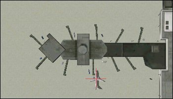
Editor of the traffic at the ports for FS2004.
→ Size:
704 KB
→ Date:
22 years ago (27.10.2003 11:00)
→ Author:
Lee Swordy
→ License:
Freeware - Free version, Unlimited Distribution
→ Downloaded:
2211 time(s)