Panel A340 Просмотр ZIP-архива
A340/Docs/Main Panel.htm
<!DOCTYPE HTML PUBLIC "-//W3C//DTD HTML 4.01 Transitional//EN">
<html>
<head>
<title>Main Panel</title>
<meta http-equiv="Content-Type" content="text/html; charset=iso-8859-1">
</head>

<body bgcolor="#00FFFF" text="#0000FF" link="#0066FF" vlink="#FF00FF">
<div align="center">
  <p><font size="+3">MAIN PANEL</font></p>
  <p><img src="Images/Main.jpg" width="800" height="600"></p>
  <p> </p>
  <table width="838" height="442" border="0">
    <tr>
      <td width="482"><font color="#0000FF" size="+2">1. Master Warning Lamp</font></td>
      <td width="346"><font size="+2">12. MFD <font size="+1">(Multi Function
        Display) </font></font></td>
    </tr>
    <tr>
      <td><font size="+2">2. Master Caution Lamp</font></td>
      <td><font size="+2">13. Standby Airspeed Indicator</font></td>
    </tr>
    <tr>
      <td><font size="+2">3. Nav1 OBS Course Indicator and Adjuster</font></td>
      <td><font size="+2">14. Standby Altimeter</font></td>
    </tr>
    <tr>
      <td><font size="+2">4. Altimeter Barometer Indicator and Adjuster</font></td>
      <td><font size="+2">15. Standby Artificial Horizon</font></td>
    </tr>
    <tr>
      <td><font size="+2">5. Flight Director Switch</font></td>
      <td><font size="+2">16. Upper EICAS Display</font></td>
    </tr>
    <tr>
      <td><font size="+2">6. GPS Switch <font size="+1">(Slaves Nav To GPS)</font></font></td>
      <td><font size="+2">17. Landing Gear Handle</font></td>
    </tr>
    <tr>
      <td><font size="+2">7. MFD Control Panel</font></td>
      <td><font size="+2">18. Window Icons</font></td>
    </tr>
    <tr>
      <td><font size="+2">8. RMI VOR1/ADF1 Switch</font></td>
      <td><font size="+2">19. EICAS Control Switches</font></td>
    </tr>
    <tr>
      <td height="42"><font size="+2">9. RMI VOR2/ADF1 Switch</font></td>
      <td><p><font size="+2">20. RMI</font></p>
        </td>
    </tr>
    <tr>
      <td><font size="+2">10. Autopilot Control Panel</font></td>
      <td><font size="+2">21. Lower EICAS Display</font></td>
    </tr>
    <tr>
      <td><font size="+2">11. PFD <font size="+1">(Primary Flight Display)</font></font></td>
      <td><font size="+2"> </font></td>
    </tr>
  </table>
  <p align="left"><font color="#0000FF" size="+3">1. MASTER WARNING LAMP-</font><font color="#0000FF" size="+2">
    This lamp will light and a flashing description in <font color="#FF0000">red</font>
    of the warning will appear on the MFD when the aircraft enters a STALL or
    OVERSPEED condition. The warning can be cleared by clicking on the Master
    Warning Lamp.</font></p>
  <p align="left"><font color="#0000FF" size="+3">2. MASTER CAUTION LAMP- </font><font color="#0000FF" size="+2">This
    lamp will light and a flashing description in <font color="#FFFF00">yellow</font>
    of the caution will appear on the MFD when the aircraft enters a LOW FUEL,
    TERRAIN or SINKRATE condition. The caution can be cleared by clicking the
    Master Caution Lamp.</font></p>
  <p align="left"><font size="+3">3. NAV1 OBS-</font><font size="+2"> The course
    selection for Nav 1 is displayed and selected here.</font></p>
  <p align="left"><font size="+3">4. ALTIMETER BAROMETER-</font><font size="+2">
    The barometer setting for the altimeter is set and displayed here. By clicking
    on the center of the knob, this will set the current sea level barometric
    pressure into the altimeter. If the aircrafts flight level is above 180000
    ft the the standard of 29.92 will be set into the altimeter. The value can
    also be adjusted at the Standby Altimeter (14). If you click the knob to the
    left the reading will display Inches of Mercury (in Hg) to the right and the
    display will read in Millibars (MB).</font></p>
  <p align="left"><font size="+3">5. FLIGHT DIRECTOR SWITCH-</font><font size="+2">
    This will turn the flight director bars on the PFD (11) on and off.</font></p>
  <p align="left"><font size="+3">6. GPS SWITCH-</font><font size="+2"> This will
    slave the NAV 1 to the GPS unit with the switch on.</font></p>
  <p align="left"><font size="+3">7. MFD CONTROL PANEL-</font><font size="+2">
    This is where the many features of the MFD (Multi Function Display) (12) are
    controlled.</font></p>
  <p align="center"><img src="Images/MFD_PANEL.jpg" width="257" height="173"></p>
  <p align="center"><font size="+2">The MFD control panel consist of 3 sections,
    the rotary switch on the left is to select the type of display on the MFD.
    There is LS (Landing System), VOR, NAV, ARC and Plan. These will be described
    in detail below. The rotary knob on the right is to select the range of the
    display of the flight plan when in the PLAN mode. These are in NM (Nautical
    Miles) 10 thru 320. The buttons along the top are to select the items which
    are displayed in the flight plan when in the PLAN mode. CSTR is for the course
    track of the flight plan. WPT will display all the intersections within view
    of the plan. ARPT will display the airports, VORD displays the VOR and DME
    stations. The NDB displays the ADF stations.</font></p>
  <p align="center"> </p>
  <p align="center"><font size="+2">LS is for the Landing System display. This
    will give you a large and easy to read display of the ILS (Instrument Landing
    Systems) Vertical (course) and Horizontal (glide path) Bars. The dark blue
    needle points to the ADF station if being received. The light blue triangle
    is your Autopilot Heading Bug.</font></p>
  <p align="center"><img src="Images/MFD_ILS.jpg" width="371" height="364"></p>
  <p align="center"> </p>
  <p align="center"> </p>
  <p align="center"><font size="+2">VOR gives you a large easy to read indicator
    of where the tuned in VOR stations are in reference to the aircraft. This
    is very handy for setting up approaches. </font></p>
  <p align="center"><img src="Images/MFD_VOR.jpg" width="368" height="353"></p>
  <p align="center"> </p>
  <p align="center"> </p>
  <p align="center"><font size="+2">The NAV selection gives you a indication of
    your reference to the in flight navigation aids. The NAV 1 OBS needle shows
    the omni radial selected for VOR 1. This is selected by the Nav1 OBS Course
    Adjuster (3). The CDI (Course Deviation Indicator) bar shows your position
    in reference to the selected radial. NAV 2 points to the location of VOR 2
    in reference to the aircraft. The ADF needle points to the tuned in NDB.</font></p>
  <p align="center"><img src="Images/MFD_NAV.jpg" width="364" height="356"></p>
  <p align="center"> </p>
  <p align="center"> </p>
  <p align="center"><font size="+2">ARC is like the NAV selection except it is
    presented in a close up view. The indicators are similar and have the same
    functions as the NAV display. There is the added feature of a Track Indicator,
    this indicates the aircrafts current track along the ground. This takes the
    aircrafts present bearing and add the effect of the winds on the aircraft.</font></p>
  <p align="center"><img src="Images/MFD_ARC.jpg" width="368" height="357"></p>
  <p align="center"> </p>
  <p align="center"> </p>
  <p align="center"><font size="+2">The PLAN display shows you the reference of
    the aircraft to the filed flight plan of the current flight. The area represented
    in the Plan Display is selected by the Range rotary switch. It will display
    in 10, 20, 40, 80, 160 and 320 Nautical Miles. The range setting is shown
    below the aircraft indicator when in PLAN display mode. The picture below
    shows how the different items in the plan is represented.</font></p>
  <p align="center"><img src="Images/MFD_PLAN.jpg" width="373" height="364"></p>
  <p align="center"> </p>
  <p align="center"><font size="+2">Note: Additional MFD information will follow
    below at item 12. MFD (Multi Function
    Display)</font></p>
  <p align="left"><font size="+3">8. RMI VOR1/ADF1 SWITCH-</font><font size="+2">
    This will select if the RMI's (</font> <font size="+2">Radio Magnetic Indicator)
    (20) primary needle will point to the VOR 1 or ADF 1.</font></p>
  <p align="left"><font size="+3">9. RMI VOR2/ADF1 SWITCH-</font><font size="+2">
    This will select if the RMI's (</font> <font size="+2">Radio Magnetic Indicator)
    (20) secondary needle will point to the VOR 2 or ADF 1.</font></p>
  <p align="left"><font size="+3">10. AUTOPILOT CONTROL PANEL</font></p>
  <p align="center"><img src="Images/AP.jpg" width="806" height="216"></p>
  <table width="995" height="317" border="0">
    <tr>
      <td width="496"><div align="left"><font color="#0000FF" size="+1">1. Indicates
          if in Mach or Speed (IAS) mode.</font></div></td>
      <td width="489"><div align="left"><font color="#0000FF" size="+1">12. Engages
          the autothrotlle. Must be on for the speed command to work.</font></div></td>
    </tr>
    <tr>
      <td><div align="left"><font color="#0000FF" size="+1">2. Displays the selected
          Mach or IAS number.</font></div></td>
      <td><div align="left"><font color="#0000FF" size="+1">13. Displays the selected
          heading value.</font></div></td>
    </tr>
    <tr>
      <td><div align="left"><font color="#0000FF" size="+1">3. Selects between
          Mach or Speed Mode.</font></div></td>
      <td><div align="left"><font color="#0000FF" size="+1">14. Shows if the altitude
          is in feet or meters.</font></div></td>
    </tr>
    <tr>
      <td><div align="left"><font color="#0000FF" size="+1">4. To adjust the Mach
          or IAS value.</font></div></td>
      <td><div align="left"><font color="#0000FF" size="+1">15. The target altitude
          selected for Alt Hold.</font></div></td>
    </tr>
    <tr>
      <td><div align="left"><font color="#0000FF" size="+1">5. Engages the Speed
          command. </font></div></td>
      <td><div align="left"><font color="#0000FF" size="+1">16. Selects the target
          altitude for Alt Hold.</font></div></td>
    </tr>
    <tr>
      <td><div align="left"><font color="#0000FF" size="+1">6. Engages the Approach
          hold. </font></div></td>
      <td><div align="left"><font color="#0000FF" size="+1">17. Engages Altitude
          Hold </font></div></td>
    </tr>
    <tr>
      <td height="35">
        <div align="left">
          <p><font color="#0000FF" size="+1">7. Allows for flying a Back Course
            (reversed) approach. Note there is no glideslope lock in this mode.</font></p>
        </div></td>
      <td><div align="left"><font color="#0000FF" size="+1">18. Shows if the vertical
          speed is in feet per minute or meters per minute.</font></div></td>
    </tr>
    <tr>
      <td><div align="left"><font color="#0000FF" size="+1">8. Locks in the Nav
          hold to fly the OBS to or from a VOR.</font></div></td>
      <td><div align="left"><font color="#0000FF" size="+1">19. Indicates the
          vertical speed value selected.</font></div></td>
    </tr>
    <tr>
      <td><div align="left"><font color="#0000FF" size="+1">9. To adjust the Heading
          hold value.</font></div></td>
      <td><div align="left"><font color="#0000FF" size="+1">20. Selects either
          Feet or Meters for the Altitude and VS values.</font></div></td>
    </tr>
    <tr>
      <td><div align="left"><font color="#0000FF" size="+1">10. Engages the heading
          hold. </font></div></td>
      <td><div align="left"><font color="#0000FF" size="+1">21. Selects the Vertical
          speed value.</font></div></td>
    </tr>
    <tr>
      <td height="27">
<div align="left"><font color="#0000FF" size="+1">11. AP1 turns on the autopilot.
          AP2 is inop.</font></div></td>
      <td><div align="left"><font color="#0000FF" size="+1">22. Engages the Vertical
          Speed hold. Will also be active when Alt Hold is selected.</font></div></td>
    </tr>
  </table>
  <p align="left"> </p>
  <p align="left"><font size="+3">11. PFD (Primary Flight Display)- </font><font size="+2">The
    PFD displays all the critical flight environment information. Here you will
    see the aircrafts attitude (pitch and bank). The airspeed and altitude. The
    heading and autopilot inputs.</font></p>
  <p align="center"><img src="Images/PFD.jpg" width="658" height="614"> </p>
  <table width="777" height="437" border="0">
    <tr>
      <td width="392"><font color="#0000FF" size="+2">1. Indicated Airspeed</font></td>
      <td width="375"><font color="#0000FF" size="+2">14. Altitude indicator strip
        X 100</font></td>
    </tr>
    <tr>
      <td><font color="#0000FF" size="+2">2. AP Alt Hold engaged</font></td>
      <td><font color="#0000FF" size="+2">15. Flight director bars</font></td>
    </tr>
    <tr>
      <td><font color="#0000FF" size="+2">3. AP NAV Hold engaged</font></td>
      <td><font color="#0000FF" size="+2">16. Aircraft pitch and bank reference</font></td>
    </tr>
    <tr>
      <td><font color="#0000FF" size="+2">4. AP Approach Hold engaged</font></td>
      <td><font color="#0000FF" size="+2">17. Mach overspeed indicator</font></td>
    </tr>
    <tr>
      <td><font color="#0000FF" size="+2">5. AP Back Course engaged</font></td>
      <td><font color="#0000FF" size="+2">18. Airspeed indicator strip</font></td>
    </tr>
    <tr>
      <td><font color="#0000FF" size="+2">6. AP 1 Active</font></td>
      <td><font color="#0000FF" size="+2">19. Selected Airspeed bug</font></td>
    </tr>
    <tr>
      <td><font color="#0000FF" size="+2">7. Flight Director is engaged</font></td>
      <td><font color="#0000FF" size="+2">20. Artificial Horizon</font></td>
    </tr>
    <tr>
      <td><font color="#0000FF" size="+2">8. Autothrottle is engaged</font></td>
      <td><font color="#0000FF" size="+2">21. Current Altitude</font></td>
    </tr>
    <tr>
      <td><font color="#0000FF" size="+2">9. Altitude selection bug</font></td>
      <td><font color="#0000FF" size="+2">22. Current Mach number</font></td>
    </tr>
    <tr>
      <td><font color="#0000FF" size="+2">10. Bank Indicator</font></td>
      <td><font color="#0000FF" size="+2">23. Gyro Compass</font></td>
    </tr>
    <tr>
      <td><font color="#0000FF" size="+2">11. Slip Indicator</font></td>
      <td><font color="#0000FF" size="+2">24. Current Heading</font></td>
    </tr>
    <tr>
      <td><font color="#0000FF" size="+2">12. Vertical speed bug</font></td>
      <td><font color="#0000FF" size="+2">24. Altimeter barometric setting</font></td>
    </tr>
    <tr>
      <td><font color="#0000FF" size="+2">13. Current Vertical speed</font></td>
      <td><font color="#0000FF" size="+2"> </font></td>
    </tr>
  </table>
  <p align="center"> </p>
  <p align="left"><font size="+3">12. MFD (Multi Function Display)- </font><font size="+2">Most
    of the feature of the MFD where covered in above under the MFD Control Panel.
    Some of the other features are shown here. These features are found on all
    the MFD selected displays.</font></p>
  <p align="center"><img src="Images/MFD_add.jpg" width="538" height="531"></p>
  <table width="913" height="293" border="0">
    <tr>
      <td width="440"><font color="#0000FF" size="+2">1. Current Ground Speed</font></td>
      <td width="428"><font color="#0000FF" size="+2">10. Distance to the next
        waypoint </font></td>
    </tr>
    <tr>
      <td><font color="#0000FF" size="+2">2. True Airspeed</font></td>
      <td><font color="#0000FF" size="+2">11. Local time on reaching the next
        waypoint </font></td>
    </tr>
    <tr>
      <td><font color="#0000FF" size="+2">3. Wind Vector Component</font></td>
      <td><font color="#0000FF" size="+2">12. Vor 1 Needle style</font></td>
    </tr>
    <tr>
      <td><font color="#0000FF" size="+2">4. Wind Velocity</font></td>
      <td><font color="#0000FF" size="+2">13. VOR station tuned to NAV 1</font></td>
    </tr>
    <tr>
      <td><font color="#0000FF" size="+2">5. Indicates if NAV 1 is to the VOR
        or GPS</font></td>
      <td><font color="#0000FF" size="+2">14. NAV1 DME</font></td>
    </tr>
    <tr>
      <td><font color="#0000FF" size="+2">6. Current Heading</font></td>
      <td><font color="#0000FF" size="+2">15. Aircraft reference indicator</font></td>
    </tr>
    <tr>
      <td><font color="#0000FF" size="+2">7. Indicates if Approach Hold is active</font></td>
      <td><font color="#0000FF" size="+2">16. NAV2 DME</font></td>
    </tr>
    <tr>
      <td><font color="#0000FF" size="+2">8. Next waypoint in the flight plan</font></td>
      <td><font color="#0000FF" size="+2">17. VOR station tuned to NAV 2</font></td>
    </tr>
    <tr>
      <td><font color="#0000FF" size="+2">9. Bearing to the next waypoint</font></td>
      <td><font color="#0000FF" size="+2">18. Vor 2 Needle style</font></td>
    </tr>
  </table>
  <p align="center"> </p>
  <p align="left"><font size="+3">13. Standby Airspeed Indicator- </font><font size="+2">Back
    up airspeed indicator in case of electrical failure.</font></p>
  <p align="left"><font size="+3">14 Standby Altimeter-</font><font size="+2">
    Back up altimeter in case of electrical failure.</font></p>
  <p align="left"><font size="+3">15. Standby Artificial Horizon- </font><font size="+2">Back
    up artificial horizon in case of electrical failure.</font></p>
  <p align="left"><font size="+3">16. Upper EICAS Display-</font> <font size="+2">There
    are two displays for the upper EICAS (Engine Indication and Crew Alerting
    System) these are selected by the ECAM switch (19). The first display (Data)
    gives you the primary engine instruments. EPR (Engine Pressure Ratio), N1,
    EGT (Exhaust Gas Temperature), N2 and Fuel flow in 1000's of pounds per hour.
    Total Fuel on Board in pounds a flap indicator and readout in degrees. It
    also display the state of several switches and the hydraulic pressure, parking
    brake and if the spoilers are armed.</font></p>
  <p align="center"><img src="Images/UPPER_EICAS_1.jpg" width="548" height="531"></p>
  <p align="center"> </p>
  <p align="center"><font size="+2">The second display (Engines) shows you a graphical
    display of EPR,N1,EGT and N2.</font></p>
  <p align="center"><img src="Images/UPPER_EICAS_2.jpg" width="538" height="531"></p>
  <p align="center"> </p>
  <p align="center"> </p>
  <p align="left"><font size="+3">17. Landing Gear Handle-</font> <font size="+2">Used
    to deploy and retract the landing gear, the landing gear indicator lights
    are covered in the Lower Main Panel section.</font></p>
  <p align="left"><font size="+3">18. Window Icons-</font> <font size="+2">Used
    to select the other available windows.</font></p>
  <p align="center"><img src="Images/ICONS.jpg" width="478" height="319"></p>
  <p align="center"> </p>
  <p align="left"><font size="+3">19. EICAS Control Switches- </font><font size="+2">Used
    to select the displays of the Upper and Lower EICAS.</font></p>
  <p align="left"><font size="+3">20. RMI (</font> <font size="+3">Radio Magnetic
    Indicator)-</font><font size="+2"> Displays the direction of VOR 1, VOR 2
    and ADF 1 relative to the aircraft. It also will display NAV1 and NAV2 DME.</font></p>
  <p align="center"><img src="Images/RMI.jpg" width="559" height="319"></p>
  <p align="center"> </p>
  <p align="left"><font size="+3">21. Lower EICAS Display- </font><font size="+2">This
    will display 4 different modes, Flight Controls, Fuel Status, Hydraulic System
    and Access Doors. These are selected by the EICAS Control Switches (19). Also
    displayed at the bottom of each of the EICAS screens is the Turbine inlet
    Air Temp, Outside Air Temp, AP Altitude selected, Autobrake setting and the
    Grosse Weight if the aircraft.</font></p>
  <p align="center"><font size="+2">The Flight Control display will show the current
    position of the Ailerons, Elevator and the Rudder. It will also show the current
    Elevator Pitch Trim setting, if the Spoilers are armed and if the spoilers
    are deployed.</font></p>
  <p align="center"><img src="Images/LOWER_EICAS_1.jpg" width="510" height="490"></p>
  <p align="center"> </p>
  <p align="center"><font size="+2">The Fuel Status Display shows the total amount
    if fuel used in pounds, the status of the master fuel switches to each engine,
    the status of the crossfeed valves, the amount of fuel in each tank in pounds,
    the temperature of the fuel in each tank and if the tank heaters are on. It
    shows the total current fuel flow from all the engines. The status of the
    fuel dump valve and the total fuel remaining. The tanks are arranged from
    left to right as Left Aux, Left Main, Center 2, Center 1, Center 3, Right
    Main and Right Aux.</font></p>
  <p align="center"><img src="Images/LOWER_EICAS_2.jpg" width="510" height="490"></p>
  <p align="center"> </p>
  <p align="center"><font size="+2">The Hydraulic system display gives the avaiable
    hydraulic fluid for each engine in percent, the pressure from each engine
    and the total sytem pressure.</font></p>
  <p align="center"><img src="Images/LOWER_EICAS_3.jpg" width="510" height="490"></p>
  <p align="center"> </p>
  <p align="center"><font size="+2">The Access will display the status of the
    Passenger Door, Galley Door and Fwd & Aft Cargo doors.</font></p>
  <p align="center"><img src="Images/LOWER_EICAS_4.jpg" width="510" height="490"></p>
  <p align="center"> </p>
  <p align="left"><font size="+2">This completes the Main panel section.</font></p>
  <p align="left"><font size="+2"><a href="Start%20Here.htm">Start Menu</a></font>
  </p>
  </div>
</body>
</html>
39804-A340.zip
| Имя файла | Дата | Размер |
|---|---|---|
| A340/ | 03.08.2011 06:22 | |
| A340/Docs/ | 03.08.2011 06:22 | |
| A340/Docs/Images/ | 03.08.2011 06:22 | |
| A340/Docs/Images/AP.jpg | 18.06.2005 06:16 | 29 KB |
| A340/Docs/Images/files.jpg | 22.06.2005 19:05 | 14 KB |
| A340/Docs/Images/FIP_1.jpg | 19.06.2005 11:37 | 19 KB |
| A340/Docs/Images/FIP_2.jpg | 19.06.2005 11:38 | 19 KB |
| A340/Docs/Images/FIP_3.jpg | 19.06.2005 11:39 | 20 KB |
| A340/Docs/Images/FIP_4.jpg | 19.06.2005 11:51 | 16 KB |
| A340/Docs/Images/gauges.jpg | 17.06.2005 09:18 | 14 KB |
| A340/Docs/Images/ICONS.jpg | 18.06.2005 09:05 | 16 KB |
| A340/Docs/Images/Image1.jpg | 17.06.2005 08:25 | 102 KB |
| A340/Docs/Images/Image2.jpg | 22.06.2005 16:54 | 88 KB |
| A340/Docs/Images/LOWER_EICAS_1.jpg | 18.06.2005 09:32 | 22 KB |
| A340/Docs/Images/LOWER_EICAS_2.jpg | 22.06.2005 17:14 | 27 KB |
| A340/Docs/Images/LOWER_EICAS_3.jpg | 22.06.2005 17:15 | 18 KB |
| A340/Docs/Images/LOWER_EICAS_4.jpg | 22.06.2005 17:16 | 18 KB |
| A340/Docs/Images/LOWER_PANEL.jpg | 22.06.2005 17:01 | 85 KB |
| A340/Docs/Images/LOW_ICON.jpg | 17.06.2005 09:02 | 1005 B |
| A340/Docs/Images/Main.jpg | 22.06.2005 17:05 | 104 KB |
| A340/Docs/Images/MFD_add.jpg | 18.06.2005 08:20 | 23 KB |
| A340/Docs/Images/MFD_ARC.jpg | 18.06.2005 05:18 | 34 KB |
| A340/Docs/Images/MFD_ILS.jpg | 18.06.2005 04:10 | 29 KB |
| A340/Docs/Images/MFD_NAV.jpg | 18.06.2005 04:25 | 31 KB |
| A340/Docs/Images/MFD_PANEL.jpg | 18.06.2005 03:50 | 11 KB |
| A340/Docs/Images/MFD_PLAN.jpg | 18.06.2005 05:51 | 36 KB |
| A340/Docs/Images/MFD_VOR.jpg | 18.06.2005 04:17 | 30 KB |
| A340/Docs/Images/OH_ICON.jpg | 17.06.2005 09:03 | 1 KB |
| A340/Docs/Images/OVERHEAD.jpg | 19.06.2005 09:46 | 175 KB |
| A340/Docs/Images/PEDESTAL.jpg | 19.06.2005 11:10 | 179 KB |
| A340/Docs/Images/PED_ICON.jpg | 17.06.2005 09:03 | 1 KB |
| A340/Docs/Images/PFD.jpg | 18.06.2005 07:46 | 42 KB |
| A340/Docs/Images/RADIOS.jpg | 19.06.2005 12:01 | 35 KB |
| A340/Docs/Images/RMI.jpg | 18.06.2005 09:23 | 25 KB |
| A340/Docs/Images/UPPER_EICAS_1.jpg | 22.06.2005 16:51 | 35 KB |
| A340/Docs/Images/UPPER_EICAS_2.jpg | 22.06.2005 17:13 | 25 KB |
| A340/Docs/Installation.htm | 22.06.2005 16:56 | 3 KB |
| A340/Docs/Lower Panel.htm | 22.06.2005 19:06 | 2 KB |
| A340/Docs/Main Panel.htm | 22.06.2005 17:12 | 22 KB |
| A340/Docs/Overhead.htm | 22.06.2005 17:18 | 5 KB |
| A340/Docs/Pedestal.htm | 22.06.2005 17:21 | 6 KB |
| A340/Docs/Start Here.htm | 22.06.2005 19:04 | 5 KB |
| A340/Gauges/ | 03.08.2011 06:22 | |
| A340/Gauges/ab320km_config.ini | 22.06.2005 18:32 | 2 KB |
| A340/Gauges/ab320km_fuel_dump.ini | 19.06.2005 10:14 | 933 B |
| A340/Gauges/ab320km_sound.ini | 18.06.2005 02:58 | 387 B |
| A340/Gauges/AB340KM_airspeed.gau | 18.06.2005 07:14 | 46 KB |
| A340/Gauges/AB340KM_altimeter.gau | 18.06.2005 07:14 | 31 KB |
| A340/Gauges/AB340KM_STBATT.gau | 18.06.2005 07:15 | 385 KB |
| A340/Gauges/dsd_fuel_dump.gau | 05.12.2004 14:14 | 96 KB |
| A340/Gauges/dsd_xml_config.gau | 23.04.2005 20:37 | 56 KB |
| A340/Gauges/dsd_xml_sound2.gau | 22.11.2004 23:34 | 64 KB |
| A340/Gauges/Z_AB320KM.cab | 22.06.2005 18:34 | 977 KB |
| A340/Image1.gif | 22.06.2005 18:42 | 12 KB |
| A340/Image1.jpg | 22.06.2005 18:41 | 100 KB |
| A340/Image2.jpg | 22.06.2005 18:43 | 117 KB |
| A340/Image3.jpg | 22.06.2005 18:44 | 102 KB |
| A340/Panel/ | 03.08.2011 06:22 | |
| A340/Panel/a320 panel base.bmp | 05.04.2006 00:35 | 2 MB |
| A340/Panel/a320 upper panel.bmp | 05.04.2006 00:35 | 2 MB |
| A340/Panel/a321_left135.bmp | 21.03.2003 06:08 | 769 KB |
| A340/Panel/a321_left45.bmp | 22.05.2004 02:05 | 2 MB |
| A340/Panel/a321_left90.bmp | 21.03.2003 06:08 | 769 KB |
| A340/Panel/a321_right135.bmp | 21.03.2003 06:09 | 215 KB |
| A340/Panel/a321_right180.bmp | 21.03.2003 06:08 | 769 KB |
| A340/Panel/a321_right45.bmp | 21.06.2005 08:11 | 2 MB |
| A340/Panel/a321_right90.bmp | 21.03.2003 06:09 | 215 KB |
| A340/Panel/down.bmp | 07.12.2001 20:04 | 768 KB |
| A340/Panel/ED-A320.cab | 08.04.2005 14:24 | 37 KB |
| A340/Panel/FDSFX panel blue dark (A320).bmp | 10.03.2004 23:19 | 961 KB |
| A340/Panel/FDSFX.bmp | 11.03.2004 00:19 | 961 KB |
| A340/Panel/fl.bmp | 06.04.2005 02:48 | 769 KB |
| A340/Panel/forward.bmp | 06.04.2005 20:10 | 769 KB |
| A340/Panel/fr.bmp | 05.04.2005 20:41 | 769 KB |
| A340/Panel/headup.bmp | 13.04.2004 02:05 | 769 KB |
| A340/Panel/HUD_Bkgrnd.bmp | 12.05.2005 23:33 | 196 KB |
| A340/Panel/ll.bmp | 06.04.2005 03:00 | 769 KB |
| A340/Panel/LOWER_MAIN.bmp | 22.06.2005 19:05 | 1 MB |
| A340/Panel/lr.bmp | 06.04.2005 02:40 | 769 KB |
| A340/Panel/MAIN.bmp | 22.06.2005 19:05 | 5 MB |
| A340/Panel/main2.bmp | 12.05.2005 23:12 | 2 MB |
| A340/Panel/OVERHEAD.bmp | 21.06.2005 21:49 | 3 MB |
| A340/Panel/Panel.cfg | 07.05.2010 04:43 | 12 KB |
| A340/Panel/PEDESTAL.bmp | 21.06.2005 08:17 | 1 MB |
| A340/Panel/post.bmp | 06.04.2005 20:05 | 769 KB |
| A340/Panel/rb.bmp | 05.04.2005 21:11 | 769 KB |
| A340/Panel/rr.bmp | 06.04.2005 03:30 | 769 KB |
| A340/Panel/Thumbs.db | 08.04.2005 13:49 | 34 KB |
| A340/README.txt | 19.06.2005 12:44 | 146 B |
| A340/Sound/ | 03.08.2011 06:22 | |
| A340/Sound/a340/ | 03.08.2011 06:22 | |
| A340/Sound/a340/a340_xml_00.wav | 09.01.1998 01:55 | 32 KB |
| A340/Sound/a340/a340_xml_01.wav | 08.06.2000 22:00 | 79 KB |
| A340/Sound/a340/a340_xml_02.wav | 26.06.2004 02:36 | 10 KB |
| A340/Sound/a340/a340_xml_03.wav | 26.06.2004 02:36 | 79 KB |
| A340/Sound/a340/a340_xml_04.wav | 26.06.2004 02:36 | 150 KB |
| A340/Sound/a340/a340_xml_05.wav | 26.06.2004 02:36 | 18 KB |
| A340/Sound/a340/a340_xml_06.wav | 11.05.2000 16:47 | 14 KB |
| A340/Sound/a340/a340_xml_07.wav | 12.02.2004 17:48 | 90 KB |
| avsim_su.diz | 03.08.2011 07:25 | 406 B |
| Итого: | 39 MB | |
Panel A340
| Rating: 3.7!
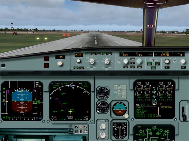
Long sought frishnuyu panel A340.Nashel panel, but some were missing Gough, Gough found and gathered all in one paket.Reshil share with you, someone may also need to be. PS Package assembled by avsim.com
→ Size:
9 MB
→ Date:
14 years ago (03.08.2011 06:34)
→ Author:
Ken Mitchell
→ Approved by moderator:
Lenya69
→ License:
Freeware - Free version, Unlimited Distribution
→ Downloaded:
2329 time(s)